


SECTION 1
PRODUCT DESCRIPTION
PV-225208 Photovoltaic Inverter
Operation and Maintenance Manual
Copyright 2003, Xantrex Technology Inc.
DOCUMENT: 151811
1-4
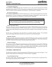
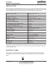
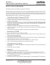
egatloVeniLCAlanimoN%21-%01+,CAV802
tnerruCeniLCAmumixaM )egatlovenilwolta(SMRA596
ycneuqerFeniLlanimoNzH7
.0-5.0+,zH06
rewoPtuptuOCAsuounitnoC esahP3CAV802@Wk0.522
egatloVmumixaMVPCDV006
wodniWgnikcarTrewoPkaePCDV
006-*033
egatloVgnikcarTrewoPkaePmuminiMVPCDV033
tnerruCgnitarepOmumixaMVPCDA017
tnerruCtiucriCtrohSyarrAVPmumixaMCDA0011
noitarugifnoCVP dednuorgevitagenraloponoM
erutarepmeTgnitarepOC°05ot02-**
erutarepmeTegarot
SC°05ot04-
gnitaRerutarepmeTtneibmAmumixaMC°05
ytidimuHevitaleRgnisnednoc-noN,%59oT
noitavelEteef006,6evobad
etareD
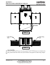
)sehcnini(snoisnemiD72X201X78
thgieW.sbl5391.xorppA
epyTerusolcnER3AMEN
eliFgnitsiLLU653991E-eliF
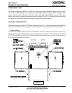
EQUIPMENT SYMBOL
Chassis ground – Customer supplied system ground connection point. This symbol may be found near
a stud within the main enclosure. It is provided as a location to bond the electrical system equipment
ground.
*Dependent on actual AC line voltage. Refer to Section 4 for detail on the minimum power tracking voltage.
**If ambient temperature is between -20 to 0° C, the unit must be powered up in standby for at least one
hour prior to going on-line.
SPECIFICATIONS
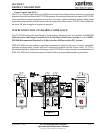
The PV-225208 has been designed for photovoltaic power systems, which operate within the following speci-
fications. Application of the PV-225208 in a manner inconsistent with these specifications may cause damage
to the PV-225208 and other system components, and is a violation of the terms of the warranty.