


Installation
Remote Sensing
Release 1.1 45
Remote Sensing
The power supply regulates the output voltage at the output connectors in its normal
configuration without remote sense lines connected.
Remote sensing lets the power supply track and regulate the output voltage at the
load, and thereby compensate for the voltage drop in the load lines. The power
supply will only compensate within the limitations of its voltage rating, to a
maximum of 5V per load line. Remote sensing is normally only required for critical
loads which cannot tolerate the slight voltage drop in the load lines caused by their
resistance. Remote sensing has no effect when the power supply is operating in
Constant Current mode.
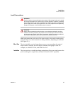
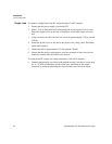
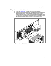
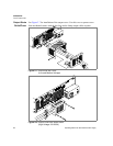
Two remote sensing connectors are located on the rear panel of the power supply. See
Figure 1.3, on page 20 for location and polarity. Connect 2 wires from these ports to
the load, where the power supply cables terminate for your connection. Carefully
observe the correct polarity when making the connection.
The remote sensing input is sensitive to electrical noise, so always use a shielded
twisted pair, 22AWG or greater for the sense line cable. Terminate the shield to the
supply chassis or the negative output of the power supply for best results.