


5
A
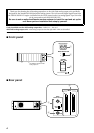
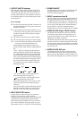
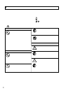
OUTPUT UNIT ID indicator
This indicator displays the ID number of the OUT-
PUT connector of the DSP unit DSP1D/DSP1D-EX
connected to the AO8. If an error occurs in the con-
nection to the DSP1D, or if the unit does not lock to
the wordclock signal, one of the following error indi-
cations appears.
Error message
E2
: The AO8 is connected to the INPUT connector of
the DSP1D/DSP1D-EX. Connect the AO8 to the
OUTPUT connector.
E3
: A cable is disconnected from the INPUT A, B, or
C connector on the rear panel, or the connection
is made incorrectly. If the connection is proper,
replace the cable.
UL
: The unit does not lock to the wordclock signal.
UC
: The control signal is not being received correctly.
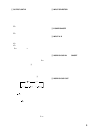
“
O
.
x
.
”:(two dots and the ID number of the OUTPUT
connector on the DSP1D/DSP1D-EX)
Illuminating dots means that the AO8 is con-
nected in Mirror mode from the DSP1D/DSP1D-
EX.
If “
O
.
x
.
” lights up continuously during Mirror
mode operation, the INPUT SELECTOR switch
(
2
) setting matches the setting controlled from
the CS1D and the system is operating normally.
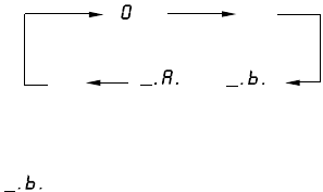
If the control signal from the CS1D has changed
the setting during Mirror mode operation and it
does not match the INPUT SELECTOR switch
(
2
) setting any more, this indicator changes in
the following order.
“_.
A
.” means that the control signal from the
CS1D has changed the setting to “A”
“ ” means that the control signal from the
CS1D has changed the setting to “B.”
During this time period, you can connect or dis-
connect the cable from the unselected output
connector.
If you set the INPUT SELECTOR switch so that it
matches the setting made via the control signal
from the CS1D, “
O
.
x
.
” lights up continuously.
B
INPUT SELECTOR switch
Use this switch to select an input source from the
INPUT A or B connector on the rear panel.
During the Mirror mode operation, the control signal
sent from the CS1D has priority, and the INPUT
SELECTOR switch is disabled. In this case, the OUT-
PUT UNIT ID indicator shows the status. For more
information, refer to
1
OUTPUT UNIT ID indicator.
C
POWER ON/OFF
Use this switch to turn the power to the AO8 on and
off. When the power is turned on, the OUTPUT
UNIT ID indicator lights up.
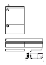
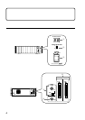
D
INPUT connectors A and B
These connectors are used to input multi-channel dig-
ital audio signals from the DSP1D/DSP1D-EX. Use
the INPUT SELECTOR switch
2
on the front panel
to select an input source (INPUT A or INPUT B). Be
sure to use the included genuine Yamaha half-pitch
68-pin cable for connection. Optional genuine
Yamaha cables in a variety of lengths are also available.
E
WORD CLOCK IN jack, ON/OFF switch
The WORD CLOCK IN jack is used to provide the
word clock to the AO8 from a clock generator or a
connected external device. Use a BNC cable with an
impedance of 75
Ω
for connection.
The WORD CLOCK ON/OFF switch is used to termi-
nate the word clock connection. Basically, if the AO8
is the last device of the word clock chain, or if nothing
is connected to the WORD CLOCK IN/OUT jacks, set
this switch to ON.
F
WORD CLOCK OUT jack
The WORD CLOCK OUT jack is used to provide
word clock from the AO8 to the connected external
device, such as a digital MTR or a DAT recorder. Use a
BNC cable with an impedance of 75
Ω
for connection.
“. .”
“ .x.”
“. .”
“ ”(
“”)