


ANALOG IN
CH2B
B
SIGNAL
MIC/LINE INPUT CARD
MODEL LMY2-ML
B
SIGNAL
CH2A CH1B CH1A
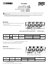
When the indicator is lit in orange, channel B is selected.
When the indicator is turned off, channel A is selected.
The green LED lights up
at 34 dB before clipping.
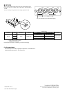
ANALOG IN
CH4
SIGNAL
SIGNAL
AD CARD
MODEL LMY4-AD
SIGNAL
SIGNAL
CH3 CH2 CH1
The green LED lights up at 34 dB before clipping.
Input Actual Load For Use With
Input Level
Connector
Terminals Impedance Nominal
Nominal Max. Before Clip
CH 1-4 10 kΩ 600 Ω Lines +10 dB (2.45 V)* +24 dB (12.3 V)* XLR-3-31 type (Balanced)**
* 0 dB is referenced to 0.775 Vrms.
** 1=GND, 2=HOT, 3=COLD
AD Conversion: 24 bit linear +4 bit floating, 128 times oversampling.
I/O cards
for
ANALOG OUTPUT BOX
ANALOG INPUT BOX
MIC/LINE INPUT CARD LMY2-ML
AD CARD LMY4-AD
DA CARD LMY4-DA
T
hank you for choosing the Yamaha input card for the analog input box AI8, and the Yamaha output card for the analog
output box AO8.
Be sure to ask an authorized Yamaha service engineer to install the cards. Do not install the cards yourself.
The connecting screw also functions as the ground. Secure the screw tightly.
■ LMY2-ML
This is a two-channel analog input card. Set the input level in the range
of –68 dB to +10 dB.
You can install up to eight cards in the analog input box AI8.
Input
GAIN***
Actual Load For Use With
Input Level
Connector
Terminals Impedance Nominal
Nominal Max. Before Clip
CH1A, CH1B
–68 dB
3 kΩ
50-600 Ω Mics
–68 dB (309 µV)* –54 dB (1.55 mV)*
XLR-3-31 type
CH2A, CH2B
+10 dB
& 600 Ω Lines
+10 dB (2.45 V)* +24 dB (12.3 V)*
(Balanced)**
* 0 dB is referenced to 0.775 Vrms.
** 1=GND, 2=HOT, 3=COLD
*** The GAIN control level displayed on the CS1D.
+48VDC (phantom power) is individually supplied to each input connectors.
AD Conversion: 24 bit linear +4 bit floating, 128 times oversampling.
■ LMY4-AD
This is a four-channel analog input card.
You can install up to eight cards in the analog input box AI8.