


ENGLISH
Part Names and Functions
MY16-EX Owner’s Manual
5
■
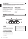
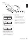
Switches
Set these switches as appropriate for your situation and for the device in which the card is installed.
A
Daisy-chain connection ID (SW1)
Assign an ID number to each card in the daisy-chain in
sequence, starting with the card closest to the master card
(such as the MY16-ES64).
B
Sampling Frequency (SW2)
NOTE:
This card supports only Double Speed mode when
running at 88.2/96kHz. (Double Channel mode is not
supported.)
C
Card ID (SW3)
Typically set this switch to the [Emu.] position. If you set
this switch to the [Emu.] position and switch
2
(SW2) to
the [48K] position, the host device will recognize the card
as a Yamaha MY16-AT digital I/O card. If you set this
switch to the [Emu.] position and switch
2
(SW2) to the
[96K] position, the host device will recognize the card as a
Yamaha MY8-AE96 digital I/O card. If you install the card
in a host device whose firmware supports the MY16-EX,
setting this switch to the [Nat.] position enables you to
make best use of the MY16-EX function.
D
SW104/SW105
Leave these switches permanently set to the [OFF]
position during use. Please do not change the settings.
Otherwise, the card will not operate properly.
Word Clock Master settings on the host device
If the MY16-EX and the master card (MY16-ES64 etc.) are
installed in the same device, do not select the MY16-EX as the
clock master.
If the MY16-EX and the master card (MY16-ES64, etc.) are
installed in a different device, you can select the MY16-EX as
the clock master. In this case, the word clock signal input to the
[MASTER SIDE IN] connector will be recognized as the master
clock. If multiple MY16-EX cards are installed, select the
MY16-EX with the lowest ID number as the clock master.
123
SW3SW2SW1
Emu.96K48K321 Nat.
4
SW105
SW104
OFF
OFF
Mode
Position
No.1 1
No.2 2
No.3 3
Mode
Position
44.1/48 kHz 48K
88.2/96 kHz 96K
Mode
Position
Emulation Emu.
Native Nat.