


5
PAL
44.1 K
ON
UP
4%
REF V
RSVD
NTSC
48 K
OFF
DOWN
0.1%
AE
IN7/8
1 2
4
5
3
REF
VIDEO
INPUT
OUTPUT
I/O INTERFACE CARD MODEL MY8-AEB
MADE IN JAPAN
7/8 5/6 3/4 1/2
7/8 5/6 3/4 1/2
12
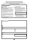
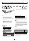
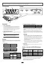
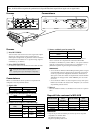
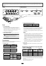
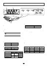
The MY8-AEB is an eight-channel digital input/output card that complies with the AES 3id-1995 standard. It provides video
input jacks that allow the host device in which the MY8-AEB is installed to be synchronized to a video signal.
Panel Switches
Panel
1
REF VIDEO jack
This is a video input jack used to generate a word clock
synchronized to the video signal. It has the capability of
maintaining the word clock even if the video signal is
interrupted. In order to use this word clock, set switch
4
to the
REF V position.
2
INPUT/OUTPUT jacks
These are AES 3id-1995 compliant input and output jacks.
Switches
Set these switches as appropriate for your situation and for the device
to which this unit is connected.
1
Video Signal
2
Basic Fs
3
Fs Factors
Do not input signals other than in this format.
Doing so may damage the device.
Mode Position
PAL PAL
NTSC NTSC
Mode Position
44.1 kHz 44.1 K
48 kHz 48 K
Mode (Fs / Basic Fs)
Position
OFF/ON DOWN/UP 0.1% / 4%
25/24 (+4%)
ON UP
4%
1001/1000 (+0.1%) 0.1%
1 (Basic Fs) OFF
1000/1001 (–0.1%)
ON DOWN
0.1%
24/25 (–4%) 4%
4
Ch7/8 Word Clock Source
This switch selects the word clock source that is provided as Ch 7/8 of the
host device in which the MY8-AEB is installed.
If this switch is set to the REF V position, you will be able to use the
word clock that is generated from the video signal. Use switches
1
–
3
to
specify the conditions for the word clock that is generated.
NOTE:
• If this is set to REF V, the word clock will continue to be provided
from the MY8-AEB even if the video signal is interrupted or if a
problem occurs with the input waveform. However, the word clock
status indicator for channel 7/8 of the host device slot in which the
MY8-AEB is installed will display an error such as SYNC ERROR to
indicate that a problem has occurred.
• If this is set to REF V and there is no signal being input to INPUT 7/8,
the channel status indication (e.g., emphasis) for that channel of the
host device may not be displayed correctly.
5
Reserved
Leave this switch permanently set to the AE position for use.
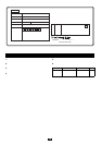
Host devices in which the MY8-AEB can be
installed
NOTE:
•For the latest information on host devices in which the MY8-AEB can be
installed, refer to the Yamaha Pro Audio website.
Yamaha Pro Audio global web site:
http://www.yamahaproaudio.com/
Mode Position
Synthesized from REF VIDEO REF V
INPUT 7/8 IN7/8
Model name
# of Usable
cards
Model name
# of Usable
cards
DME32 3 01V96 1
DIO8 8 DME24N 1
DM2000 6 DME64N 4
02R96 4 PM5D/PM5D-RH 4
DM1000 2 M7CL-48/32 3