


6
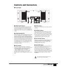
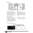
■ Rear Panel
8 DC PARALLEL INPUT Connector
This connector is used to connect two PW5000 units in
parallel. Two PW5000’s can be connected in this way to
distribute the power load, thus reducing the load on each
unit, and to ensure uninterrupted failsafe operation in the
even that one unit shuts down.
Use only the optional PSL5000 Power Supply Link
Cable for this connection. Rotate the connector ring to
the left to connect, or to the right to disconnect.
9 DC OUTPUT Connector
Use this connector to connect the PW5000 to the
PM5000 console. When using parallel-connected
PW5000 units, this connector connects to the DC
PARALLEL INPUT connector on the main PW5000
unit. Always use the cable supplied with the PM5000
console to connect the PW5000 to the console.
A second PW5000 should be parallel-connected to the
main PW5000 only using the optional PSL5000 Power
Supply Link Cable. Rotate the connector ring to the left
to connect, or to the right to disconnect.
) EARTH Screw Terminal
For maximum safety be sure to securely attach a
confirmed earth line to this terminal. An earth line is also
included in the power supply cable, so the unit will be
properly earthed if the AC outlet used is earthed. If the
AC outlet is not earthed be sure to properly connect the
EARTH terminal. Proper earthing not only ensures
safety, but it also guarantees minimum noise from hum
and interference.
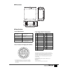
Rack-mounting holes are provided near the rear
edges of the side panels. When rack-mounting the
PW5000, be sure to use mounting hardware that is
the correct size for the rack, and attach securely at
both the front and rear ends of the unit.
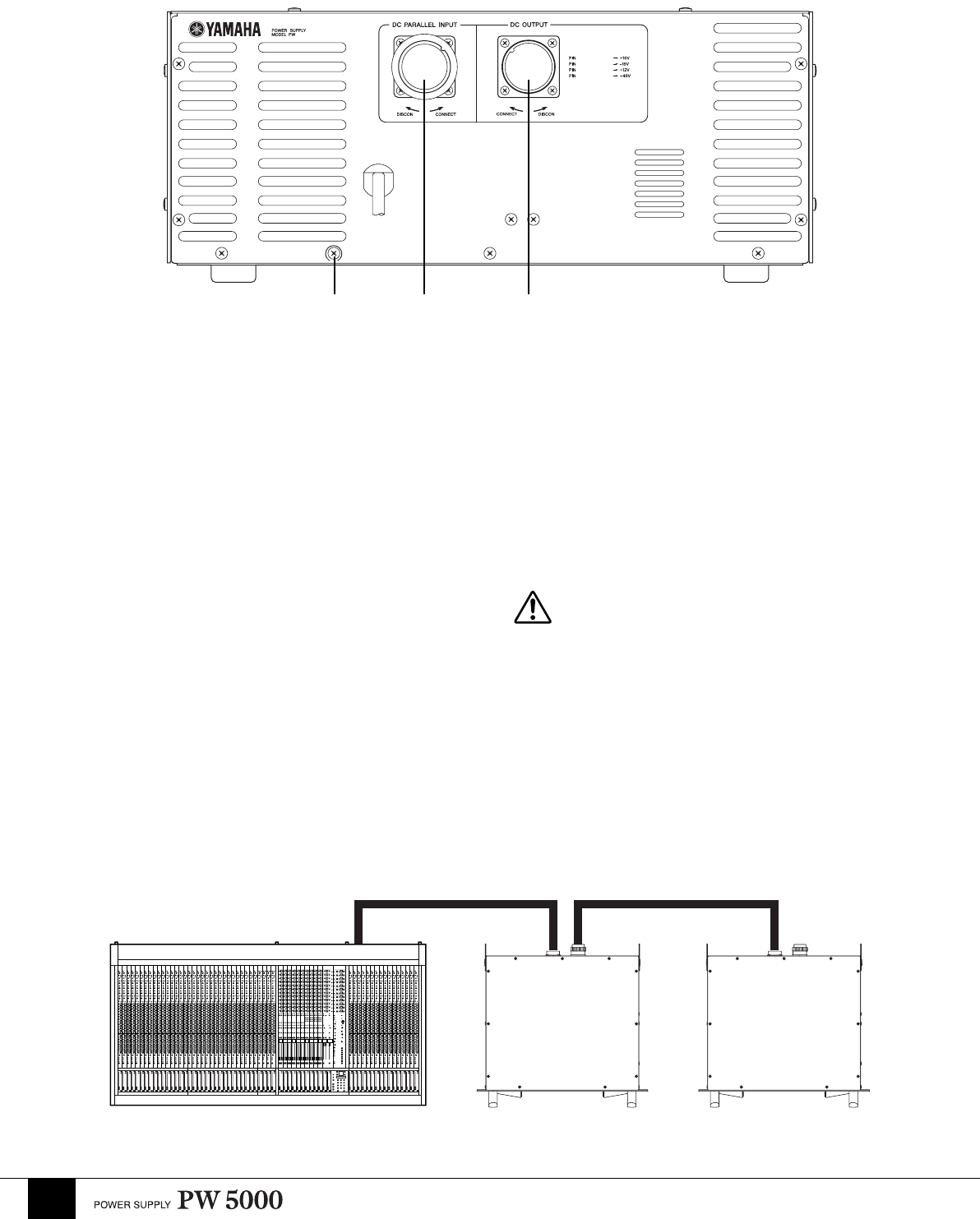
Parallel-connected PW5000 Power Supplies
13.5A
13.5A
14.0A
1.0A
5000
9,10,14,15
1,2,4,5
22,23,25,26,27
19
8) 9
PM5000 PW5000 PW5000
DC
OUTPUT
DC
OUTPUT
DC PARALLEL
INPUT
Optional PSL5000 power Supply Link Cable.