


®
RKC INSTRUMENT INC.
The first edition: JUN. 2006 [IMQ00]
The second edition: DEC. 2006 [IMQ00]
HEADQUARTERS: 16-6, KUGAHARA 5-CHOME, OHTA-KU TOKYO 146-8515 JAPAN
PHONE: 03-3751-9799 (+81 3 3751 9799) E-mail: info@rkcinst.co.jp
FAX: 03-3751-8585 (+81 3 3751 8585) DEC. 2006
Modbus is a registered trademark of Schneider Electric.
The name of each programmable controller (PLC) means the products of each manufacturer.
Company names and product names used in this manual are the trademarks or registered
trademarks of the respective companies.
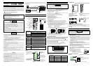
3.3 Contents of the Communication Port
The contents of the modular connector signal are all the same from COM. PORT1 to COM. PORT4.
RS-422A RS-485A
Pin No. Signal name Symbol
Pin No. Signal name Symbol
1 Receive data R (A)
1 Send/receive data T/R (A)
2 Receive data R (B) 2 Send/receive data T/R (B)
3 Signal ground SG 3 Signal ground SG
4 Send data T (B) 4 Unused
5 Send data T (A) 5 Unused
6 Signal ground SG 6 Signal ground SG
The six-pin type modular connector should be used for the connection to the Z-COM
module. (Recommended manufacturer and model: Hirose Electric, TM4P-66P)
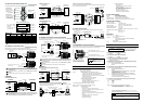
3.4 Example of Connection to PLC
Up to four SRZ units can be multi-drop connected to one PLC communication port.
Customer is requested to prepare a communication cable fit for the Z-COM to be connected by the PLC.
Programmable
controller (PLC)
SRZ unit 1
SRZ unit 2
Connected to
COM. PORT3
Connected to
communication port
Connected to
COM.PORT3
Connected to
COM.PORT4
W-BF-02*
SRZ unit 3
(4 units maximum)
W-BF-01*
* Communication cable (RKC product)
is sold separately.
If communication errors occur frequently due to the operation environment or the
communication distance, connect termination resistors to the Z-COM module and
the other party unit.
For termination resistor of Z-COM modules, see 3.6
Z-COM Module Termination
Resistor.
For the termination resistor of PLC side, see the PLC Instruction Manual.
RS-422A
MITSUBISHI MELSEC series
1
R (A)
R (B)
SG
T (B)
T (A)
SG
2
3
4
5
6
RS-422A
SDB
SDA
SG
RDB
RDA
(
−
)
(+)
(
−
)
(+)
Shielded twisted pair wire
Paired wire
Z-COM module
COM. PORT3
PLC MITSUBISHI
MELSEC series
(Modular connector)
When preparing a cable of connecting the computer link module belonging to the
MITSUBISHI MELSEC series to our Z-COM module, cross each pair of wires the A
and B terminal positions on their terminal boards are not symmetrical.
OMRON SYSMAC series
1
R (A)
R (B)
SG
T (B)
T (A)
SG
2
3
4
5
6
SDB
SDA
SG
RDB
RDA
RS-422A
(
−
)
(+)
(
−
)
(+)
Shielded twisted pair wire
Paired wire
Z-COM module
COM. PORT3
OMRON PLC
SYSMAC series
(Modular connector)
RS-485
MITSUBISHI MELSEC series
SDB
SDA
SG
RDB
RDA
*R
RS-485
1
2
3
4
5
6
T/R (A)
T/R (B)
SG
SG
(−)
(+)
PLC MITSUBISHI
MELSEC series
Shielded twisted
pair wire
Paired wire
Z-COM module
COM. PORT3
(Modular connector)
*R: Termination resistor
(PLC side)
3.5 Example of Connection to the Host Computer
Up to 16 SRZ units can be connected to a host computer communication port. The communication
cable must be provided by the customer.
SRZ unit 1
SRZ unit 2
Connected to
COM.PORT1
RS-232C/RS-422A converter
COM-A (RKC product)
W-BF-02*
Host computer
Connected to
communication
connector
Connected to
COM.PORT1
Connected to
COM.PORT2
W-BF-28*
Connected to
COM.PORT1
Connected to
COM.PORT2
W-BF-02*
SRZ unit 3
(16 units maximum)
RS-422A
RS-232C
* Communication cable (RKC product)
is sold separately.
If communication errors occur frequently due to the operation environment or the
communication distance, connect termination resistors to the Z-COM module and
the other party unit.
For termination resistor of Z-COM modules, see 3.6 Z-COM Module Termination
Resistor.
For the termination resistor of PLC side, see the PLC Instruction Manual.
RS-422A
When the interface of host computer is RS-422A
1
R (A)
R (B)
SG
T (B)
T (A)
SG
T (A)
T (B)
SG
R (A)
R (B)
2
3
4
5
6
RS-422A
(
−
)
(+)
(−)
(+)
Shielded twisted pair wire
Paired wire
Host computer
Z-COM module
COM. PORT1
(Modular connector)
When the interface of host computer is RS-232C (RS-232C ↔ RS-422A)
When the interface of host computer is RS-232C, connect the RS-232C/RS-422A converter
between the host computer and the Z-COM.
COM
Host
computer
Z-COM
RS-232C/RS-422A converter
COM-A (RKC product)
RS-422A
RS-232C
D-SUB 9P
connector
Connected to
COM. PORT1
Connected to
COM. PORT2
Connected to
communication
connector
W-BF-28*
W-BF-02*
Connected to
COM. PORT1
*
Communication cable (RKC product) is
sold separately.
When the host computer has a USB connector
When the host computer has a USB connector, connect the USB communication converter between
the host computer and the Z-COM module.
Host computer
USB communication
converter COM-K
(RKC product)
Connected to USB
port of a personal
computer
USB cable
(COM-K accessory)
Connected to
USB connector
of COM-K
The termination
resistor is built
in to the
COM-K.
RS-422A
1
SG
2
4
3
5
T (A)
T (B)
Shielded twisted
pair wire
Z-COM module
COM. PORT1
(Modular connector)
1
R (A)
R (B)
SG
T (B)
T (A)
SG
2
3
4
5
6
R (A)
R (B)
Paired wire
(
−
)
(+)
(
−
)
(+)
Loader communication
Connect a USB communication converter between the host computer and the Z-COM module.
Host computer
USB communication converter
COM-K (RKC product)
Connected to
USB port of a
personal computer
Connected to
USB connecter
The termination
resistor is built in
to the COM-K.
COM
Loader communication cable
(W-BV-01)
[Option]
Connected to loader
communication connector
of the Z-COM module
Connected to
loader
communication
connecter
USB cable (COM-K accessory)
3.6 Z-COM Module Termination Resistor
If communication errors occur frequently due to the operation environment or the communication
distance, connect termination resistors to the Z-COM module and the other party unit.
When multidrop connected,
connect a termination resistor to
the Z-COM module at the farthest
end of the communication line.
• When the COM. PORT1 is used:
Insert the termination resistor to COM. PORT2.
W-BW-01 (For RS-485)
W-BW-02 (For RS-422A)
[120
Ω
1/2 W]
•
When the COM. PORT3 is used:
Insert the termination resistor to COM. PORT4.
Termination resistor connector
(Sold separately)
4. SPECIFICATIONS
PLC communication
Interface: Base on RS-422A, EIA standard
Base on RS-485, EIA standard
Protocol: • MITSUBISHI MELSEC series special protocol (type 4)
− A compatible, 1C frame, ACPU common command (WR/WW)
(A series, FX2N/FX2NC series or FX3U/FX3UC series)
− A compatible, 1C frame, AnA/AnUCPU common command (QR/QW)
(AnA/QnA series, Q series)
D register, R register, W register, ZR register
• OMRON SYSMAC series special protocol
− C mode command (RD/WD)
DM register, EM register (Specify the bank No. +10),
EM register (Specify the current bank)
Communication speed: 4800 bps, 9600 bps, 19200 bps, 38400 bps
Maximum connections: Four SRZ units per communication port of PLC
Usable PLC type: • MITSUBISHI MELSEC series
− Computer link unit
AJ71UC24, A1SJ71UC24-R4, A1SJ71C24-R4, etc.
The unit which AnA/AnUCPU common command (type 4) can use.
− Serial communication unit
AJ71QC24N, A1SJ71QC24N, QJ71C24, etc.
The unit which AnA/AnUCPU common command (type 4) can use.
− Adapter
FX0N-485ADP, FX2NC-485ADP, FX3U-485ADP
− Expanded function board
FX2N-485BD, FX3U-485-BD
• OMRON SYSMAC series
− High-order link unit
C200H-LK202-V1, C500-LK203, C120-LK202-V1
(SYSMAC C series), etc.
− CPU unit with a built-in communication port
CPU unit of SYSMAC CS1 series and CJ1 series
− Serial communication board
CS1W-SCB41 (SYSMAC CS1 series),
CJ1W-SCU41 (SYSMAC CJ1 series), etc.
Host communication
Interface: Base on RS-422A, EIA standard
Base on RS-485, EIA standard
Protocol: RKC communication or Modbus-RTU
Communication speed: 4800 bps, 9600 bps, 19200 bps, 38400 bps
Maximum connections: Sixteen SRZ units per communication port of Host computer
General specifications
Power supply voltage: 24 V DC
Power supply voltage range: 21.6 V to DC 26.4 V DC
[Including power supply voltage variation]
Current consumption: 30 mA max. Rush current: 10 A or less
Allowable ambient temperature: −10 to +50 °C
Allowable ambient humidity: 5 to 95 %RH
(Absolute humidity: MAX.W.C 29.3 g/m
3
dry air at 101.3 kPa)
Installation environment conditions: Indoor use
Altitude up to 2000 m
Weight: Approx. 110 g
Standard
Safety standard: UL: UL61010-1
cUL: CAN/CSA-C22.2 No. 61010-1
CE marking: LVD: EN61010-1
OVERVOLTAGE CATEGORY II, POLLUTION DEGREE 2,
Class II (Reinforced insulation)
EMC: EN61326
C-Tick: AS/NZS CISPR11 (equivalent to EN55011)
5. MODEL CODE
Z-COM-A -
(1) (2) (3) (4) (5) (6)
Code (4) to (6) are for quick start
codes to specify software configurable
settings. If not specified, these codes
will not be printed on labels and all
settings will be factory default.
(1) Communication 1 (COM. PORT1, COM. PORT2)
4: RS-422A 5: RS-485
(2) Communication 2 (COM. PORT3, COM. PORT4)
4: RS-422A 5: RS-485
(3) Quick start code (Communication protocol selection)
N*: No quick start code (Configured as factory default)
1: Specify quick start code 1
(4) Communication 1 protocol (COM. PORT1, COM. PORT2) [Quick start code 1]
No code: No specify quick start code
1: RKC communication (ANSI X3.28)
2: Modbus
(5) Communication 2 protocol (COM. PORT3, COM. PORT4) [Quick start code 1]
No code: No specify quick start code
1: RKC communication (ANSI X3.28)
2: Modbus
3: MITSUBISHI MELSEC series special protocol (PLC communication)
AnA/AnUCPU common command (QR/QW)
(AnA/QnA series, Q series)
4: OMRON SYSMAC series special protocol (PLC communication)
5: MITSUBISHI MELSEC series special protocol (PLC communication)
ACPU common command (WR/WW)
(A series, FX2N/FX2NC series or FX3U/FX3UC series)
(6) The number of the correspondence channels (Only PLC communication)
No code: No specify quick start code
A: 16 CH
B: 32 CH
C: 48 CH
D: 64 CH
* Factory set value when there is not specification of quick start code:
Communication 1/communication 2 RKC communication
The number of the correspondence channels: 64 CH
COM. PORT1
Communication 1
Communication 2
COM. PORT3
COM. PORT2
COM. PORT4
Z-COM module internal block diagram
The
Z
-
COM module’s
COM.PORT is internall
y
connected.
Two systems are used
for communication.
1
6
Modular connector
Pin number
Communication
port
COM. PORT1
COM. PORT2
Communication 1
Connector for Host
computer or Operation
panel connection
[RS-422A/RS-485]
Communication 2
Connector for PLC, Host
computer or Operation
panel connection
[RS-422A/RS-485]
Communication
port
COM. PORT3
COM. PORT4