


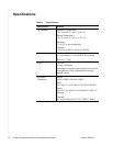

14 4000E IP Broadband Loop Carrier Installation Instructions IPD4-A2-ZZ40-20
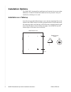
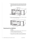
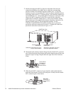
1 Identify the appropriate RJ21 Connector. Subscriber lines must be
connected according to the 4000E slot in which the corresponding
interface module was installed. Interface module slots 1–4 run from
bottom to top; the corresponding RJ21 ports are directly behind each slot
on the back of the chassis (1–4, bottom to top). Each interface module slot
on the 4000E has two corresponding RJ21 connectors on the back of the
chassis: the RJ21 connectors on the left (A) provide the subscriber
connections for interface module ports 1–24 (on most models) and the
RJ21 connectors on the right (B) provide the subscriber connections for
interface module ports 25–48 (on applicable models). For the
TIM1500-24 and EIM2000-24 interface modules, the A connectors
provide the subcriber connections for ports 1-12 and the B connectors
provide the subscriber connections for ports 13-24.
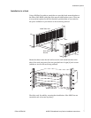
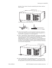
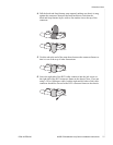
2 Detach the hook-and-loop fastener Strap from the female RJ21 connector
port: lift the hook-and-loop fastener tab from the bottom and pull the strap
upward to open, leaving it looped under the right side of the connector
frame.
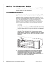
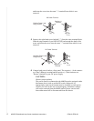
3 Slide the male RJ21 connector of your interface cable underneath the
hook-and-loop fastener, from the left, and press it firmly into the female
RJ21 connector port on the chassis.
05-17839
4000E Rear View
Interface Module B
Connectors
Interface Module A
Connectors
Subscriber connections for ports
25-48 (on applicable models)
Subscriber connections for ports
1-24 (on most models)
4A
3A
2A
1A
4B
3B
2B
1B
48V
10A
05-17840
Female RJ21
Connector A
for Interface
Module Slot 3
05-17841
Male RJ21
Connector of
Your Interface
Cable