


Connecting to Power
4929-A2-ZN20-30 4929 DSLAM Installation and User’s Guide
31
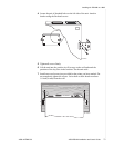
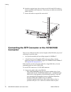
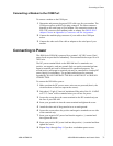
Connecting a Modem to the COM Port
To connect a modem to the COM port:
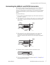
1 Determine and procure the proper DCE cable type for your modem. The
COM port requires an RJ45-type plug connector. The other connector
depends on the serial port on your modem. The connection requires an
EIA-232E crossover (null modem) cable or adapter. See DB9 to RJ45
Adapter Pinouts in Appendix A, Connectors and Pin Assignments.
2 Connect the modular plug connector of your cable to the COM port
socket.
3 Connect the other end of the cable or adapter to the serial port of your
modem.
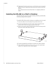
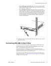
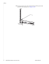
Connecting to Power
The 4900 Series DSLAM is powered by a nominal –48 VDC source. Dual
power feeds are provided for redundancy. The terminal block accepts 18 to 14
AWG wire.
The DC power terminal block on the DSLAM has five terminals: two
positive, two negative, and one ground. Only one positive terminal and one
negative terminal pair need be connected for operational purposes. The
second positive and negative terminal pair may be connected to a backup DC
power supply for redundancy. The ground terminal must be connected
regardlessly. DO NOT OPERATE THE DSLAM WITHOUT A GROUND
CONNECTION.
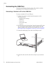
To connect the DSLAM to power:
1 Make sure that the DC power source wires are not powered (that is, the
circuit breakers or fuses are open at the source).
2 Strip about 1/2 inch (13 mm) of insulation off the ends of the 18–14 AWG
or 0.75–2.5 mm
2
solid or stranded wires you will use for power.
3 Loosen the screw above the center terminal on the DC terminal strip on
the face of your DSLAM.
4 Insert your ground wire into the center terminal and tighten the screw.
5 Attach the other end of the ground wire to an earth ground.
6 Loosen the screws above the positive and negative terminals on one side
of the terminal strip.
7 Insert your negative DC power lead into the negative (–) terminal and
then tighten the screw.
8 Insert your positive DC power lead into the positive (+) terminal and then
tighten the screw.
9 Repeat Step 6 through Step 8 if you have a redundant power source.