


A-6000 High Speed, Long Range Ethernet Wireless Bridge
Hardware Installation 2-1
Chapter 2 Hardware Installation
This chapter explains the physical ports and how to connect the hardware of A-6000.
2.1 Hardware Description
The content of the A-6000 are described below.
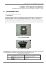
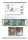
1. The outdoor unit
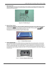
The outdoor unit has one antenna port, one data/power port and one console port. The antenna port is N-Type
female connector used to connect to the omni-directional antenna or to the RF cable then to the flat panel
antenna. The data/power port is used to link to the cable from the power injector. When the outdoor unit and the
network/power injector are connected together, the outdoor unit is turned on and initialized if the network/power
injector in the indoor is also installed successfully. The console port is only used at the initial setup and is used to
connect to the antenna alignment kit. The outward appearance of the outdoor unit are shown on Fig.2.1, 2.2 and
2.3.
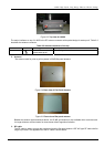
Figure 2-1 Front view of A-6000
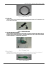
Figure 2-2 Bottom view of A-6000
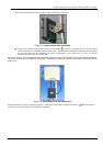
The physical interfaces on the bottom of A-6000 is the POE (Power over Ethernet) and RS-232 port. Both connectors
are special designed for water-proof. Table 2-1 describes the function of those connectors
Table 2-1 Connectors of bottom
Function Label Interface Description
Signal &
Power
8-pin female connector
with special water proof
Connecting to the indoor interface unit
supplying the power and signal
Antenna
alignment
8-pin male connector with
special water proof
Connecting to AK-100 for antenna
alignment