


Chapter 3 Hardware Overview
ES-1124 User’s Guide
24
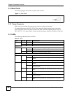
3.2 Rear Panel
The following figure shows the rear panel of the switche.
Figure 11 Rear Panel
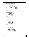
3.2.1 Power Connector
Make sure you are using the correct power source as shown on the panel.
To connect the power to the ES-1124 AC unit, insert the female end of power cord to the
power receptacle on the rear panel. Connect the other end of the supplied power cord to a
100~240V AC, 1.5A power outlet. Make sure that no objects obstruct the airflow of the fans.
3.3 LEDs
The following table describes the LEDs.
Table 2 LEDs
LED COLOR STATUS DESCRIPTION
PWR Green On The system is turned on.
Off The system is off.
Ethernet Ports
LNK/ACT Green Blinking The system is transmitting/receiving to/from an Ethernet network.
On The link to an Ethernet network is up.
Off The link to an Ethernet network is down.
Gigabit/Mini-GBIC Port
1000 Green On The port has a successful 1000 Mbps connection to a network.
Blinking The port is receiving or transmitting data to/from a 1000 Mbps
network.
Off The port is not connected to a 1000 network or the link is down.
100 Green On The port has a successful connection to a 100 Mbps Ethernet
network.
Blinking The port is receiving or transmitting data to/from a 100 Mbps
Ethernet network.
Off The port is not connected to a 100 Ethernet device or the link is
down.
10 Green On The port has a successful connection to a 10 Mbps Ethernet
network.
Blinking The port is receiving or transmitting data to/from a 10 Mbps
Ethernet network.
Off The port is not connected to a 10 Ethernet device or the link is
down.