


Dimension GS-1116A/GS-1124A Gigabit Switch
List of Figures/Tables ix
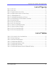
List of Figures
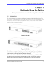
Figure 1-1 GS-1116A ...........................................................................................................................1-1
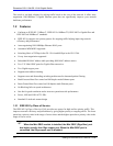
Figure 1-2 GS-1124A ...........................................................................................................................1-1
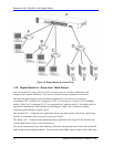
Figure 1-3 Gigabit Switch for Server Farm ..........................................................................................1-4
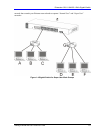
Figure 1-4 Gigabit Switch for Super User Work Groups .....................................................................1-5
Figure 2-1 Attaching Rubber Feet ........................................................................................................2-1
Figure 2-2 Attaching Mounting Brackets and Screws..........................................................................2-2
Figure 2-3 Switch Mounting to an EIA Standard 19-inch Rack...........................................................2-2
Figure 2-4 Switch Rear Panel ...............................................................................................................2-3
Figure 2-5 GS-1116A Front Panel........................................................................................................2-3
Figure 2-6 GS-1124A Front Panel........................................................................................................2-3
Figure 2-7 Transceiver Installation Procedure......................................................................................2-5
Figure
2-8 Transceiver Removal Example ...........................................................................................2-6
Figure 2-11 GS-1116A Front Panel LEDs ...........................................................................................2-7
Figure 2-12 GS-1124A Front Panel LEDs ...........................................................................................2-7
List of Tables
Table
2-1 GS-1116A/GS-1124A: Front Panel Ports ............................................................................2-3
Table 2-2 Network Cable Types...........................................................................................................2-7
Table 2-3 Front Panel LED Descriptions .............................................................................................2-7
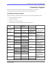
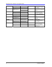
Table 3-1 Troubleshooting PWR LED .................................................................................................3-1
Table 3-2 Troubleshooting LNK/ACT LED ........................................................................................3-1
Table 3-3 Troubleshooting 1000 LEDs ................................................................................................3-1
Table 3-4 Troubleshooting Improper Network Cabling and Topology................................................3-2