PS-24 Mains Adaptor
Connect the AXIS 225FD power and alarm input/output
This document describes how to install the AXIS 225FD and the PS-24. Please refer to the
AXIS 225FD Installation Guide for further instructions.
Connect the camera to the power supply and alarm input/output* (cables not supplied). For
information on the recommended cable dimensions, please refer to the table on the PS-24
Mains Power Adaptor page.
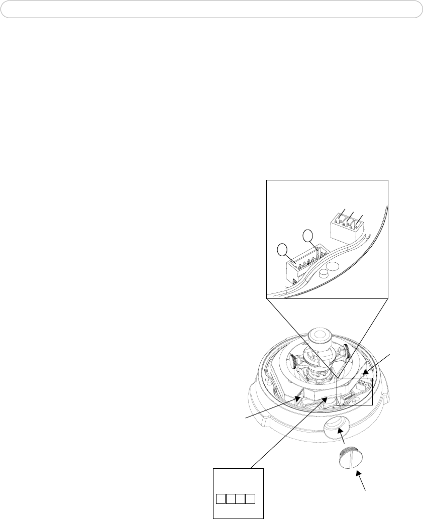
1. Disconnect the outer ring of the
cable gland, thread the cables (not
supplied) through the outer ring
and cable gland.
2. Connect the power cable from the
Terminal Connector (1) in the
PS-24 to the power connector
block in the camera.
3. Connect the input cable from the
terminal connector (2) in the PS-24
to the I/O terminal block in the
camera.
* alarm input e.g. doorbell, light and
output e.g. alarm device
Network
connector
Control
Conduit hole
and plug
LED
indicators
1
2
3
4
1
7
button
Power connector block
I/O terminal
block
G
N
D
+
o
r
AC
A
C


