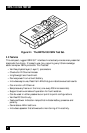
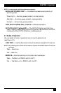
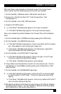
37
CHAPTER 5: Technical Reference
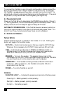
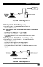
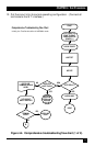
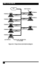
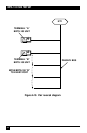
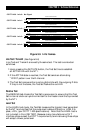
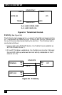
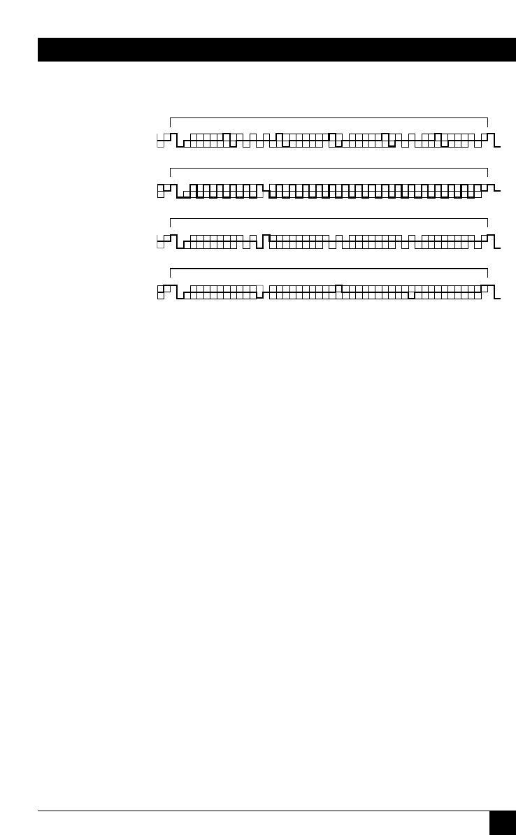
Figure 5-3. Info frames.
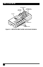
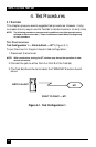
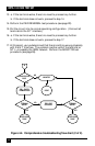
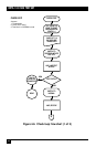
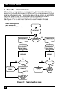
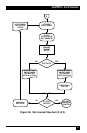
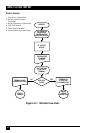
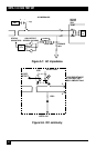
Line Test/Transmit (See Figure 5-4)
Line Test and Transmit are exactly the same test. The test is conducted
as follows.
1.Upon pressing the INITIATE button, the Test Set tries to establish
an ACTIVE link with the NT1.
2.If the ACTIVE state is reached, the Test Set sends an alternating
“101010” pattern over the D channel.
3.The Test Set compares the incoming Echo bits with the outgoing D bits.
If they’re not the same, the Test Set flashes the red LED.
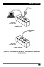
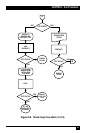
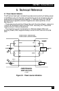
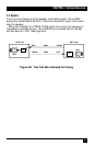
Receive Test
The RECEIVE test checks the Test Set’s receive pair to ensure that the Test
Set’s internal clock can synchronize itself to the master clock that’s provided
by the NT1.
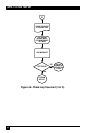
Level Test
In the LEVEL test mode, the Test Set measures the transmit level generated
by the NT1 and verifies that the pulse level is above 375mVp or -6 dB, 0 to
peak, ±10%, (per CCITT 1.430 specifications). Note that the LEVEL test is
not included in the LINE TEST. Because many manufacturers of S/T
interface chips exceed the CCITT requirements, terminals using these chips
will accept a lower pulse level.
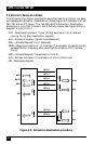
DLF
TE to NT
B1B1B1B1B1B1B1B1 L D L F L B2B2B2B2B2B2B2B2 L D LB1B1B1B1B1B1B1B1 L D L B2B2B2B2B2B2B2B2 L D LFL
D LFLB1B1B1B1B1B1B1B1 E D AFNB2B2B2B2B2B2B2B2E DS1B1B1B1B1B1B1B1B1E DS2B2B2B2B2B2B2B2B2E D LFL
D
LFLB1B1B1B1B1B1B1B1 L D LFLB2B2B2B2B2B2B2B2 L D LB1B1B1B1B1B1B1B1 L D L B2B2B2B2B2B2B2B2 L D LFL
D LFLB1B1B1B1B1B1B1B1 E D AFNB2B2B2B2B2B2B2B2E DS1B1B1B1B1B1B1B1B1E DS2B2B2B2B2B2B2B2B2E D LFL
CCITT I.430 Info 0: No Signal
CCITT I.430 Info 1:
CCITT I.430 Info 2:
CCITT I.430 Info 3:
CCITT I.430 Info 4:
48 bits in 250 microseconds
NT to TE
48 bits in 250 microseconds
TE to NT
48 bits in 250 microseconds
NT to TE
48 bits in 250 microseconds
0
1
0
0
1
0