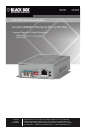
DFCS XGT+ Standalone Module
SW3 and SW4 - RESERVED
These DIP-switches are for factory use only and must always remain in the DOWN (factory
default) position.
2) INSTALL STANDALONE MODULE AND CONNECT CABLES
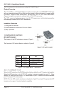
a. The XGT+ is available as a standalone module with built-in mounting brackets. For
wall-mounting, attach the XGT+ to a wall, backboard or other at surface. For tabletop
installations, place the unit on a at level surface. Attach the rubber feet to the bottom
of the XGT+ to prevent the unit from sliding. Make sure the unit is placed in a safe, dry
and secure location.
To power the unit using the AC/DC adapter, connect the AC/DC adapter to an AC outlet.
Then connect the barrel plug at the end of the wire on the AC/DC adapter to the 2.5mm
DC barrel connector (center-positive) on the unit. Conrm that the unit has powered up
properly by checking the power status LED located on the front of the unit.
To power the unit using a DC power source, prepare a power cable using a two conductor
insulated wire (not supplied) with a 14 AWG gauge minimum. Cut the power cable to the
length required. Strip approximately 3/8 of an inch of insulation from the power cable
wires. Connect the power cables to the unit by fastening the stripped ends to the DC
power connector.
Connect the power wires to the DC power source. The Power LED should indicate the
presence of power.
WARNING: Note the wire colors used in making the positive and negative connections.
Use the same color assignment for the connection at the DC power source.
NOTE: If mounting with a safety ground attachment, use the safety ground screw at the
rear of the unit.
b. Insert the appropriate 10G SFP+ or XFP transceiver (depending on the model of the
module) into Port 1 receptacle on the XGT+. The release latch of the transceiver must
be in the closed position before insertion.
c. Connect an appropriate multimode or single-mode ber cable to the ber transceiver port
on the XGT+. It is important to ensure that the transmit (Tx) is attached to the receive
side of the device at the other end and the receive (Rx) is attached to the transmit side.
d. When using copper CX4 XFP, connect the cable between the converter and external
device using the recommended copper CX4 cable.
e. Connect the RJ-45 port via a CAT 6A or better cable to a 10GBASE-T Ethernet device.
Page 6
724-746-5500 | blackbox.com