12
APPENDIX A:Cabling Pinouts
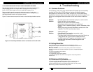
Appendix A. Cabling Pinouts
Table A-3. T568B CAT5 pinout
9
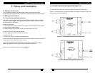
MULTI DVI SYSTEM.
5
Appendix B. Status LED’s
The Multi DVI System feature “status-at-a-glance” LED’s to ensure the units are functioning
properly and to isolate problems with input signals, units, and/or cabling thus saving time during
installation and troubleshooting. Reference the following tables for information on theses
indicators. The UTP connector also contains LED indicators on either side to provide visual cues
on connection and traffic status.
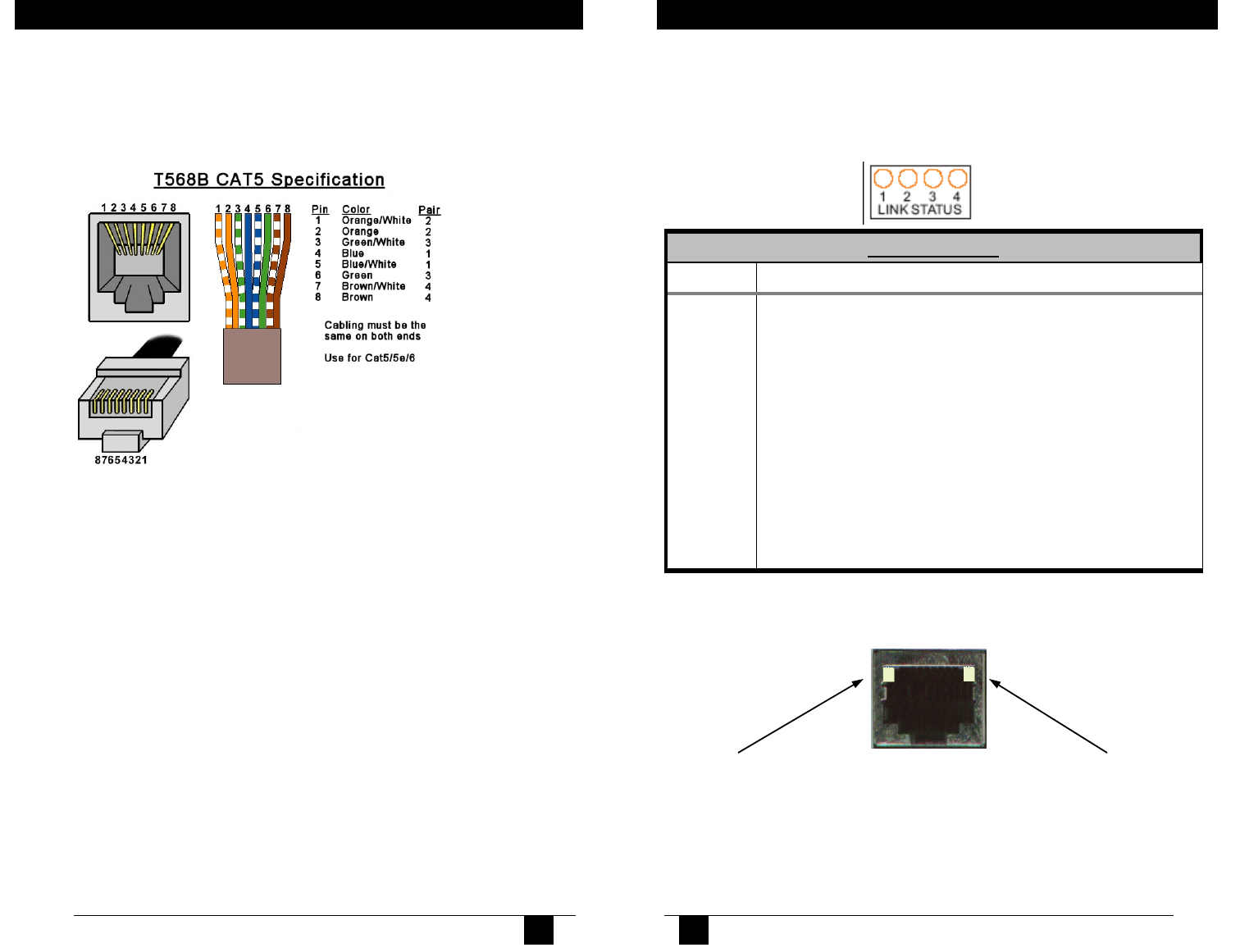
Multi DVI RJ45 UTP status Indicators:
Link Status LED’s
LED Meaning
1 Normal Operation == OFF
ON == EXCEPTION—a serious problem has occurred with
the unit. Contact Technical Support.
2 Normal Operation == ON
ON == Active DVI signal detected from source for transmitter
side OR Active DVI display detected if receiver side
3 Normal Operation == ON
Indicates active link between transmitter and receiver
4 Normal Operation == ON
Indicates video packet transmission between transmitter and
receiver
Right Side LED should be ON when
communication is established between a
transmitter and receiver. If it is off,
check cabling between the units.
Left Side LED should blink when data is
sent between transmitter and receiver. If
no blinking occurs, check DVI signal
input from the video source.
10