Manufacturer reserves the right to discontinue, or change at any time, specifications or designs without notice and without incurring obligations.
Catalog No. 532-309 Printed in U.S.A. Form 23XRV-1SI Pg CL-1 309 6-06 Replaces: New
Book 2
Ta b 5 e
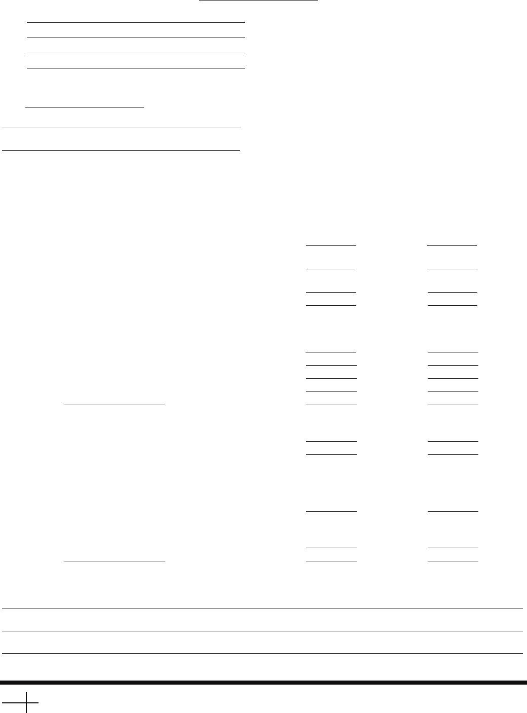
INSTALLATION START-UP REQUEST CHECKLIST
Machine Model Number: 23XRV Serial Number:
To:
Attn.:
Date
Project Name
Carrier Job Number
The following information provides the status of the chiller installation. Send a copy of this checklist to the local Carrier Service office
after it has been completed and signed-off by the Purchaser and Job Site Supervisor.
YES/NO DATE TO BE
(N/A) COMPLETED
1. The machine is level within
1
/
2
in. end to end.
2. The machine components are installed and connected in
accordance with the installation instructions.
3. The isolation package and grouting (if necessary)
are installed.
4. The relief valves are piped to the atmosphere.
5. All piping is installed and supported. Direction of flow
is indicated in accordance with the installation instructions
and job prints.
a. Chilled water piping
b. Condenser water piping
c. Waterbox drain piping
d. Pumpout unit condenser piping (if installed)
e. Other
6. Gages are installed as called for on the job prints required
to establish design flow for the cooler and condenser.
a. Water pressure gages IN and OUT
b. Water temperature gages IN and OUT
7. The machine’s control center wiring is complete. The wiring is
installed per installation instructions and certified prints.
a. Power wiring to VFD circuit breaker. (If chiller was disassembled during installation, motor leads must
not be taped until the Carrier technician megger tests
the motor.)
b. Carrier controls can independently energize water pumps
and tower fan.
c. Line side voltage is within ±10% of chiller nameplate voltage.
d. Other
COMMENTS:


