4-12
Cisco ASR 1001-X Router Hardware Installation Guide
OL-32376-02
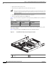
Chapter 4 Cisco ASR 1001-X Router Installation
Connecting Cables
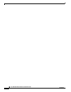
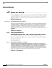
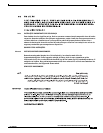
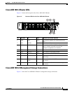
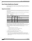
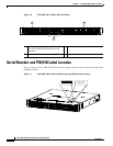
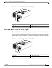
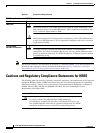
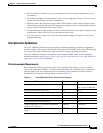
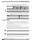
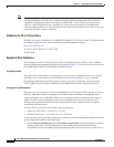
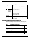
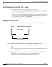
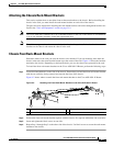
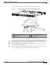
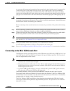
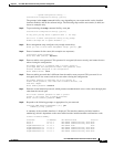
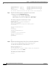
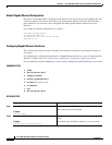
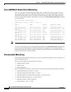
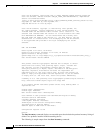
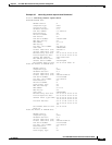
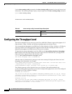
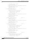
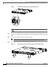
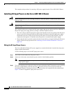
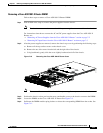
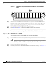
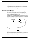
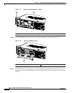
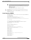
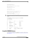
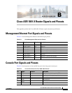
Figure 4-7 Attaching a Grounding Lug to the Chassis Ground Connector
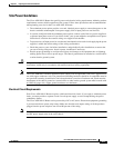
Step 5
Locate the chassis ground connector on the side of your chassis.
Step 6 Insert the two screws through the holes in the grounding lug.
Step 7 Use the Number 2 Phillips screwdriver to carefully tighten the screws until the grounding lug is held
firmly to the chassis. Do not over tighten the screws.
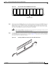
Step 8 Connect the opposite end of the grounding wire to the appropriate grounding point at your site to ensure
an adequate chassis ground.
This completes the procedure for attaching a chassis ground connection.
Connecting Cables
Keep the following guidelines in mind when connecting any external cable to the Cisco ASR 1001-X
Router:
• To reduce the chance of interference, avoid crossing high-power lines with any interface cables.
• Verify all the cabling limitations (particularly distance) before powering on the system.
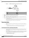
Connecting the Console and Auxiliary Port Cables
This section describes how to attach a cable to the console port or to the auxiliary ports on the Cisco
ASR 1001-X Router. The router uses RJ-45 ports for both auxiliary ports and console ports to attach a
console terminal.
The Cisco ASR 1001-X Router has an asynchronous serial (EIA/TIA-232) RJ-45 console port labeled
CON on its front panel. You can connect this port to most types of video terminals with a console cable
kit that is included with your Cisco ASR 1001-X Router. The console cable kit contains:
• One RJ-45-to-RJ-45 crossover cable
• One RJ-45-to-DB-9 (female) adapter
1 Chassis ground lead wire 3 Ground screws
2 Grounding stud 4 Chassis ground connector holes
280186
4
1
2
3