C-2
Cisco Unified IP Phone 6921, 6941, and 6961 Administration Guide for Cisco Unified Communications Manager 7.1 (SCCP)
OL-19025-01
Appendix C Technical Specifications
Cable Specifications
Cable Specifications
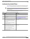
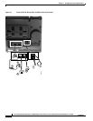
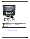
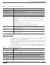
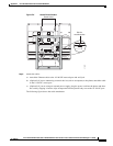
• RJ-9 jack (4-conductor) for handset and headset connection.
• RJ-45 jack for the LAN 10/100BaseT connection (labeled 10/100 SW on the Cisco Unified
IP Phone 6900 Series).
• RJ-45 jack for a second 10/100BaseT compliant connection (labeled 10/100 PC on the
Cisco Unified IP Phone 6900 Series).
• 48-volt power connector.
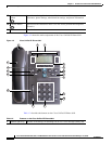
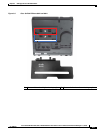
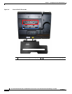
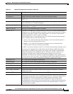
Network and Access Port Pinouts
Although both the network and access ports are used for network connectivity, they serve different
purposes and have different port pinouts.
• The network port is labeled network on the Cisco Unified IP Phone.
• The access port is labeled Computer on the Cisco Unified IP Phone.
Network Port Connector
Table C-2 describes the network port connector pinouts.
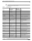
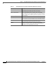
Access Port Connector
Table C-3 describes the access port connector pinouts.
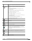
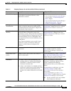
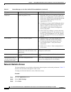
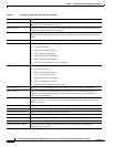
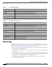
Ta ble C-2 Network Port Connector Pinouts
Pin Number Function
1 BI_DA+
2 BI_DA-
3 BI_DB+
4 BI_DC+
5 BI_DC-
6 BI_DB-
7 BI_DD+
8 BI_DD-
Note “BI” stands for bi-directional, while DA, DB, DC and DD stand for “Data A”, “Data
B”, “Data C” and “Data D”, respectively.
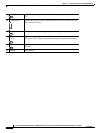
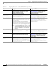
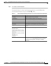
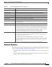
Ta ble C-3 Access Port Connector Pinouts
Pin Number Function
1 BI_DB+
2 BI_DB-
3 BI_DA+
4 BI_DD+