FLOWSEAL
3201 Walnut Avenue, Long Beach, CA 90807
562/426-2531
FAX 562/490-9546
5. Cycle the valve to the fully open position, then back to the
fully closed position, checking the actuator travel stop
settings for proper disc alignment.
6. Check the valve identification tag for valve class, materi-
als, and operating pressure to be sure they are correct for
the application.
7. Check the flange bolts or studs for proper size, threading,
and length.
The Flowseal High Performance Butterfly Valve can be
installed in the pipeline with the shaft in the vertical, horizon-
tal, or other intermediate position. Based on applications
experience, however, in media with concentrations of solid or
abrasive particles or media subject to solidification buildup,
valve performance and service life will be enhanced by
mounting the valve with the shaft in the horizontal position.
All Flowseal valves are bi-directional and can be mounted in
the pipeline in either flow direction; however, the preferred
flow direction for all seat styles and materials is with the seat
retainer ring located upstream (SUS) to provide maximum
seat protection.
1. For Wafer Style Valves:
a. Loosely install the lower flange bolts to form a cradle
between the flanges. (See Figure 1.)
b. Noting the flow direction arrow on the tag, place the
valve and flange gaskets between the flanges, making
sure the arrow on the tag points in the direction of the
flow.
c. Install the remaining flange bolts, shifting the valve as
necessary to permit the bolts to pass by or through the
valve body.
1. Remove the protective flange covers from the valve.
2. Inspect the valve to be certain the waterway is free from
dirt and foreign matter. Be certain the adjoining pipeline is
free from any foreign material such as rust and pipe scale
or welding slag that could damage the seat and disc
sealing surfaces.
3. Actuators should be mounted on the valve prior to instal-
lation to facilitate proper alignment of the disc in the valve
seat.
4. The valve should be in the closed position. Make sure
the open and closed positions of the actuator correspond
to the counter-clockwise to open direction of rotation of
the valve.
For Lug Style Valves:
a. Noting the flow direction arrow on the tag, place the
valve between the flanges, making sure the arrow on
the tag points in the direction of the flow.
b. Install the lower flange bolts loosely, leaving space for
the flange gaskets.
c. After inserting the flange gaskets, install the remaining
bolts.
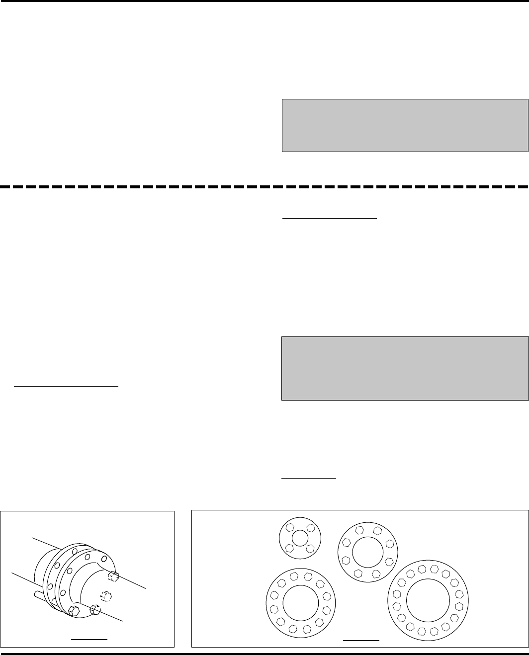
2. Using the sequence shown in Figure 2, tighten the flange
bolts evenly to assure uniform gasket compression.
3. If an actuator is to be used, air hoses or electricity should
be connected to the unit as specified by the actuator
manufacturer.
4. The valve is now ready for operation.
INSTALLATION RECOMMENDATIONS
7
CAUTION!
Remember: Install the valve with the disc in the
FULL CLOSED POSITION.
Valve Installation Procedure
Pre-Installation Procedure
1
1
1
15
8
12
4
10
6
14 2
16
7
11
3
9
5
13
8
4
6
2
7
3
5
1
8
4
6
2
11
7
3
9
5
10
12
2
3
4
Figure 1
Figure 2
Personal injury or property damage
may result if the valve is installed
where service conditions could ex-
ceed the valve ratings.
WARNING!
The Flowseal valve should be centered
between the flanges and gaskets to
prevent damage to the disc edge and
shaft as a result of the disc striking the
flange, gasket, or pipe.


