Crestron DM-DR DigitalMedia
™
Repeater
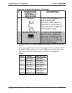
Connectors, Controls & Indicators
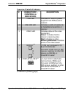
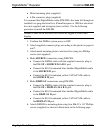
# CONNECTORS
1
,
CONTROLS &
INDICATORS
DESCRIPTION
1 PWR LED Indicates 24 Volts DC power
supplied from DMNet control
network
2 DM LINK LED Indicates a valid connection to
a DigitalMedia transmitter or
receiver
3 VIDEO LED Indicates status of the video
connection:
Green: Indicates that the
device is receiving video
Red: Indicates no video
Blinking Red/Green: Indicates
errors in the video stream
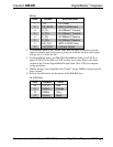
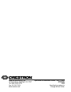
4 DISPLAY
2, 3
(1) DM port composed of (2)
8-pin RJ-45 female
Connects to DM input of a DM
receiver, switcher, or other DM
device via DM-CBL or
CresCAT-D cable
4
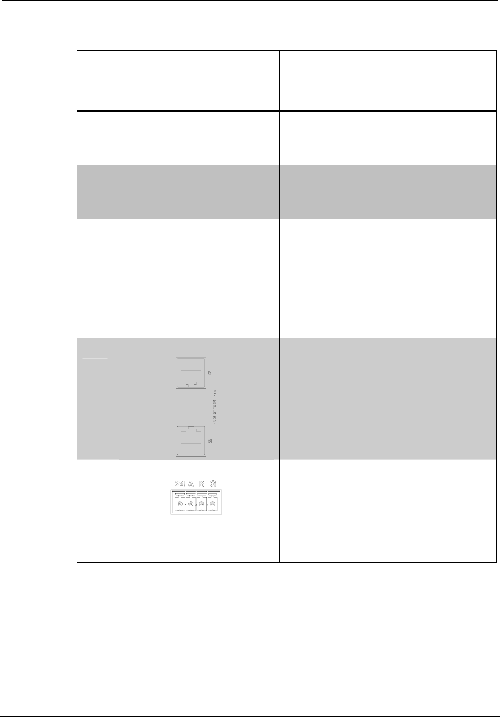
5 DISPLAY 24 A B G
5, 6
(1) 4-pin 3.5mm detachable
terminal block, DMNet port.
Connects to DMNet port of a
DM receiver, switcher, or other
DM device via DM-CBL or
CresCAT-D cable
4
(Continued on following page)
Operations & Installation Guide – DOC. 6745A DigitalMedia
™
Repeater: DM-DR • 5