Mobile Base Installation Guide
1-1
C HAPTER
1
M
OBILE
B
ASE
I
NSTALLATION
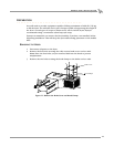
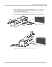
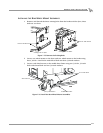
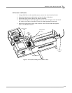
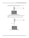
This document provides instructions for installing the mobile base to Dynojet’s Model
250 Dynamometer (dyno). To ensure safety and accuracy in the procedures, perform
the procedures as they are described.
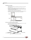
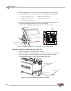
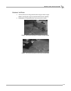
This manual will walk you through the installation procedures, wiring, and how to
secure your dyno using anchors and ground hooks.
Document Part Number: 98224105
Version 1
Last Updated: 02-14-02
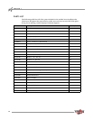
CONVENTIONS USED IN THIS MANUAL
The conventions used in this manual are designed to protect both the user and the
equipment.
TECHNICAL SUPPORT
For assistance, please contact Dynojet Technical Support at 1-800-992-3525, or write
to Dynojet at 2191 Mendenhall Drive, North Las Vegas, NV 89031.
Visit us on the World Wide Web at www.dynojet.com where Dynojet provides state of
the art technical support, on-line shopping, 3D visualizations, and press releases
about our latest product line.
example of convention description
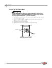
The Caution icon indicates a potential hazard to the
dynamometer equipment. Follow all procedures
exactly as they are described and use care when
performing all procedures.
The Warning icon indicates potential harm to the
person performing a procedure and/or the
dynamometer equipment.