Page 18 Epson Research and Development
Vancouver Design Center
S1D13504 Interfacing to the Motorola MPC821 Microprocessor
X19A-G-010-05 Issue Date: 01/02/02
4.3 S1D13504 Hardware Configuration
The S1D13504 uses MD15 through MD0 to allow selection of the bus mode and other
configuration data on the rising edge of RESET#. For details on configuration, refer to the
S1D13504 Hardware Functional Specification, document number X19A-A-002-xx.
The tables below show only those configuration settings important to the MPC821 interface.
.
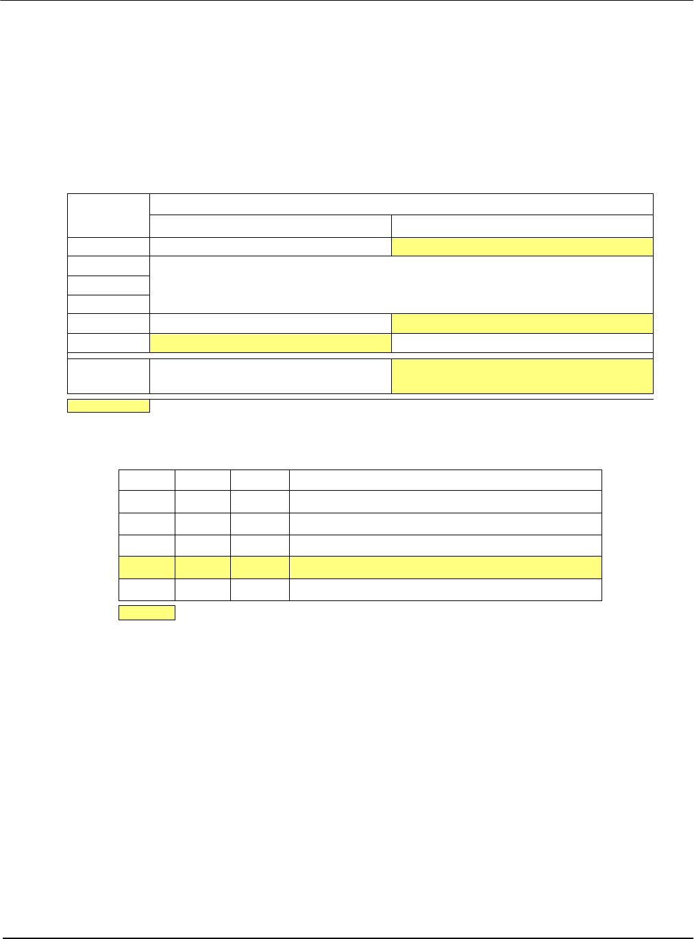
Table 4-2: Summary of Power-On/Reset Options
S1D13504
Pin Name
value on this pin at rising edge of RESET# is used to configure: (1/0)
10
MD0 8-bit host bus interface
16-bit host bus interface
MD1
For host bus interface selection see Table 4-2, “Host Bus Interface Selection” MD2
MD3
MD4 Little Endian
Big Endian
MD5 Wait# signal is active high Wait# signal is active low
MD9 Reserved
Configure SUSPEND# pin as Hardware
Suspend Enable
= configuration for MPC821 interface.
Table 4-2: Host Bus Interface Selection
MD3 MD2 MD1 Host Bus Interface
000
SH-3 bus interface
001
MC68K bus 1 interface (e.g. MC68000)
010
MC68K bus 2 interface (e.g. MC68030)
0 1 1
Generic bus interface (e.g. MPC821, ISA bus interface)
1xx
Reserved
= configuration for MPC821 interface.


