VersaTools® MDA EQ Series • Quick Start Guide
Quick Start Guide — MDA EQ Series, cont’d
VersaTools® MDA EQ Series • Table of Contents
Table of Contents
All trademarks mentioned in this manual are the properties of their respective owners.
68-978-01 Rev A
Printed in USA
09 04
Chapter 1 • Introduction ............................................ 1-1
About this Manual ....................................................... 1-2
About the MDA EQ Series Mini Distribution
Amplifiers ......................................................................
1-2
Models .................................................................................... 1-2
Features ..................................................................................1-2
Connection diagrams ............................................................ 1-3
Chapter 2 • Installation and Operation .................. 2-1
Mounting the MDA EQ Series ................................... 2-2
Tabletop use........................................................................... 2-2
Rack mounting.......................................................................2-3
Furniture mounting ............................................................... 2-4
Projector mounting ............................................................... 2-5
Rear Panel Features and Cabling.............................. 2-6
Front Panel Features and Operation ....................... 2-9
Appendix A • Specifications, Part Numbers, and
Accessories ....................................................................
A-1
Specifications................................................................ A-2
Models ............................................................................ A-4
Included Parts ...............................................................A-4
Optional Accessories ................................................... A-4
QS-2
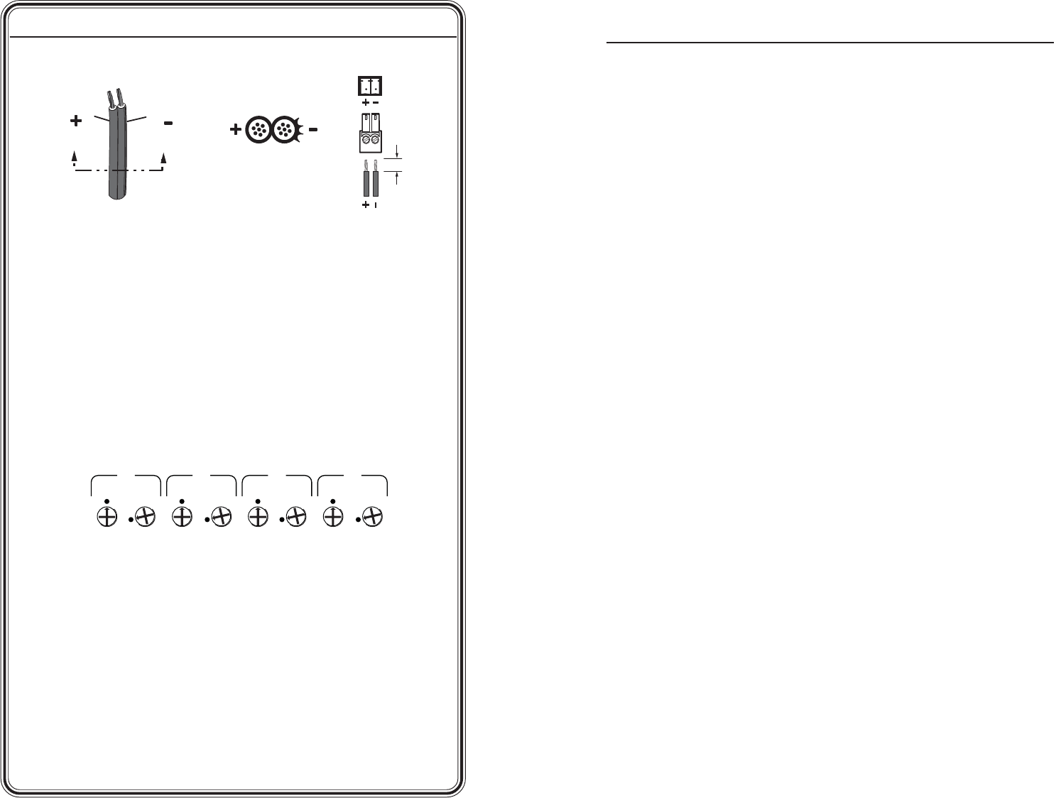
Power Supply
Output Cord
Captive Screw
Connector
0.2” (5 mm) MAX
SECTION A–A
Ridges
Smooth
AA
Wiring the power cord
Step 4
Connect power cords to the input and the outputs, and turn on the
equipment.
Step 5
Adjust the potentiometers for the outputs, using an Extron Tweeker.
If using very short output cables, set all pots to the default
setting (the arrow on the pot pointing to the dot beside it; see
illustration below).
GAIN
EQ
1
GAIN
EQ
2
GAIN
EQ
3
GAIN
EQ
4
Potentiometers at default settings
If using long cables, follow these steps:
a. Supply the Color Bars test signal to the input.
(Recommendation: Use an Extron VTG 300 Video Test
Generator to generate the test signal.)
b. Adjust the Gain pot for output 1 until the signal level at
the far end is the same as the input (or the display shows
the correct brightness and contrast).
c. Adjust the EQ pot for output 1 so that no overshoot or
round front corner appears at the far end on the scope (or
you see a sharp picture with no smearing).
d. Repeat steps 2 and 3 for the rest of the outputs.
i


