XTRA Series • Installation
Installation
XTRA Series • Installation
W
Installation and service must be performed
by authorized personnel only. See “UL rack
mounting guidelines”, on the following page.
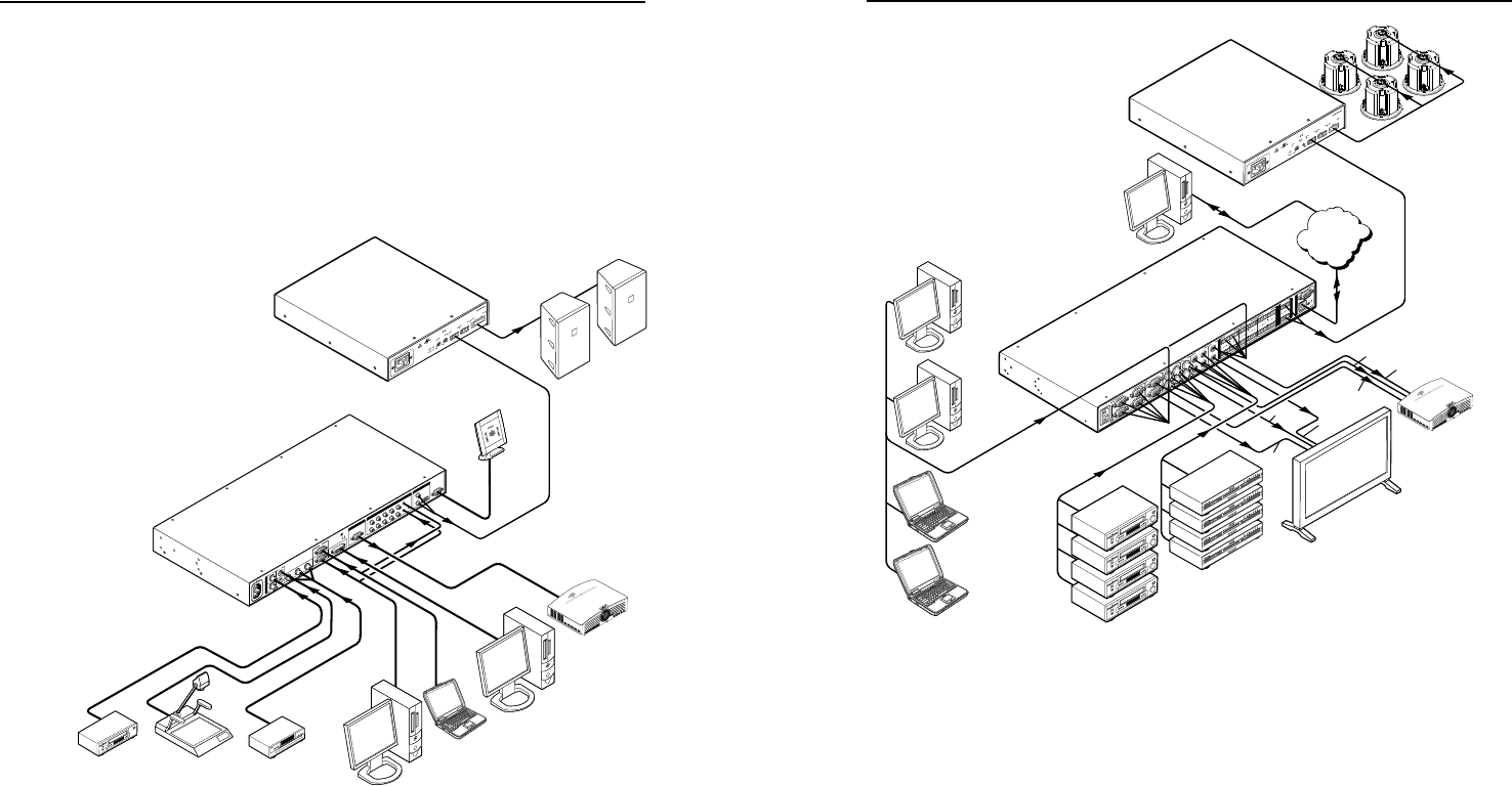
Application Examples
The following illustrations are application examples for the
XPA 1002 and the XPA 2001.
100-240V 50-60Hz
I
N
P
U
T
VID
VID
YC
Y
B-Y
R-Y
RGB
DVI
1
2
4
5
3
L
2
3
4
5
6
7
R
AUDIO INPUT
L
A
B
R
OUTPUT
L
R
OUTPUT
RGB
Y, B-Y, R-Y
8
7
RGB
6
LISTED
1T23
I.T.E.
C
U S
1
VCR
Document
Camera
RS-232
Control
LCD Projector
Laptop
DVD Player
PC
Extron
IN1508
Scaling Presentation
Switcher
PC
DVI Input
Extron
XPA 1002
Audio Power
Amplifier
100-240V 1.3A, 50-60Hz
VOL/MUTE
10V
STANDBY
4/8 OHM 50W x 2
1
2
LISTED 17TT
AUDIO/VIDEO
APPARATUS
CLASS 2 WIRING
HPA 502
C
US
LEVEL
1
12
1 2
LIMITER/
PROTECT
SIGNAL
2
INPUTS
OUTPUT
REMOTE
0
0
Extron
SI 28
Surface-mount
Speakers
XPA 1002 application example
50/60 Hz
100-240V 0.3A
L
1
R
L
2
R
L
3
R
L
4
R
L
1
R
L
2
R
L
3
R
L
4
R
L
1
R
L
2
R
L
3
R
L
4
R
L
3
R
L
4
R
I
N
P
U
T
S
O
U
T
P
U
T
S
C
O
N
T
R
O
L
I
N
P
U
T
S
O
U
T
P
U
T
S
RESET
ACTLINK
RS-232
1
2
3
4
1
5
6
7
8
19
10
11
12
1
2
2
2
COMPUTER IN COMPUTER OUT VIDEO IN S-VIDEO INOUT
OUT COMPUTER
VIDEO
S-VIDEO VARIBLE
Projector
Plasma Monitor
VCR (4)
DVD (4)
PC (2)
Laptop (2)
Extron
MPX 423
Media Presentation
Matrix
Extron
XPA 2001
Audio Power
Amplifier
TCP/IP
Network
VGA
S-video
Remote Monitoring
and Control
Video
Video
VGA
S-video
100W
VOL/MUTE
10V
STANDBY
80 Hz
L
(MONO)
R
LISTED 17TT
AUDIO/VIDEO
APPARATUS
C
US
CLASS 2 WIRING
HPA 1001
OUTPUT
70V
LEVEL
HFP
INPUTS
REMOTE
0
LIMITER/
PROTECT
SIGNAL
100-240V 1.3A, 50-60Hz
Extron
SI 26CT
Tw o-way Ceiling
Speakers
XPA 2001 Series application example
Mounting the XPA 1002 and XPA 2001
The XPA 1002 and XPA 2001 audio ampliers can be set on a
table; mounted on a rack shelf; or mounted in the plenum space
above a ceiling-mounted projector.
Tabletop use
Four self-adhesive rubber feet are included with the audio
amplifier.
For tabletop use, attach one foot at each corner of the bottom
side of the unit and place the unit in the desired location.
UL rack mounting guidelines
The following Underwriters Laboratories (UL) guidelines
pertain to the safe installation of the equipment in a rack.


