FOAMPRO® F1000
4
©2001 R11.01
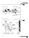
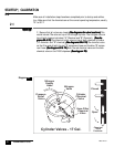
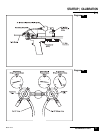
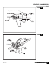
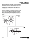
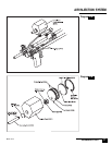
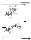
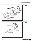
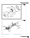
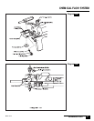
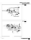
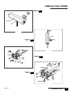
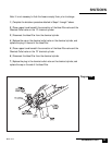
To connect the blue "B" hose to the "B" chemical cylinder: After checking to
be sure that all valves on the cylinder are closed, remove the plug from the
outlet of the chemical valve
(See diagram 5A).(See diagram 5A).
(See diagram 5A).(See diagram 5A).
(See diagram 5A). Keep the plug handy so that
it can be refitted to the cylinder after the cylinder is empty.
Remove the cap from the filter end of the blue "B" hose. Keep the plug handy it
will be needed to reseal the hose after the hose is disconnected from the
cylinder.
Connect the blue "B" hose to the outlet of the chemical valve on the "B" chemi-
cal cylinder.
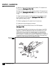
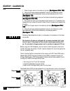
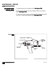
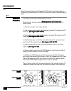
Connect the dispenser air line to an air regulator 100 to 125 psi with moisture
separator and filter.
Compressed air that contains high levels of water or oil can adversely
affect the performance and service life of some of the parts of the
Foampro dispenser. This is particularly important when using portable
compressors. Be sure to drain the compressor of any water prior to use.
Also, it is recommended that an in line air filter and moisture separator are
used to remove oil from the compressed air source.
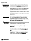
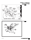
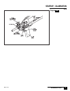
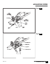
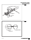
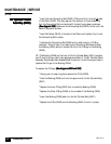
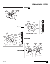
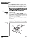
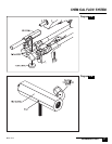
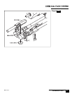
Place the nitrogen cylinder near the chemical cylinders, being sure to secure the
nitrogen cylinder so that it cannot be accidentally knocked over.
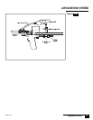
Connect the nitrogen regulator to the nitrogen cylinder using the threaded
pressure fitting on the rear of the nitrogen regulator assembly.
(See diagram 5B)(See diagram 5B)
(See diagram 5B)(See diagram 5B)
(See diagram 5B)
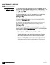
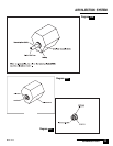
Connect the red hose leading from the nitrogen regulator assembly to the
nitrogen fitting on the "A" chemical cylinder . It will be fitted with a quick
connect fitting that will simply snap into place.
(See diagram 3B, previous(See diagram 3B, previous
(See diagram 3B, previous(See diagram 3B, previous
(See diagram 3B, previous
page)page)
page)page)
page)
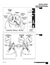
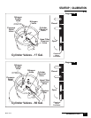
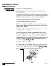
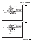
Connect the blue hose leading from the nitrogen regulator assembly to the
nitrogen fitting on the "B" chemical cylinder. It will be fitted with a quick
connect fitting that will simply snap into place.
(See diagram 5A)(See diagram 5A)
(See diagram 5A)(See diagram 5A)
(See diagram 5A)
NONO
NONO
NO
TE:TE:
TE:TE:
TE:
Connecting theConnecting the
Connecting theConnecting the
Connecting the
nitrogen hoses:nitrogen hoses:
nitrogen hoses:nitrogen hoses:
nitrogen hoses:
1.3
INSTALLATION
1.2
Connecting the blueConnecting the blue
Connecting the blueConnecting the blue
Connecting the blue
"B" hose to the "B""B" hose to the "B"
"B" hose to the "B""B" hose to the "B"
"B" hose to the "B"
chemical cylinder:chemical cylinder:
chemical cylinder:chemical cylinder:
chemical cylinder: