3–2 P485 MODBUS TO PROFIBUS CONVERTER – USER GUIDE
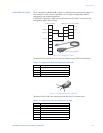
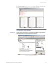
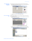
DATA EXCHANGE
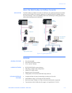
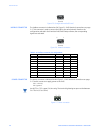
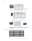
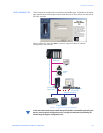
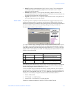
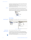
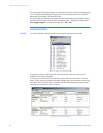
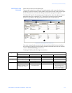
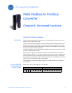
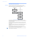
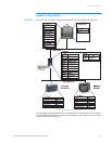
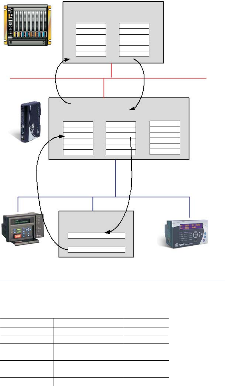
Figure 3-2: Data exchange overview
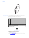
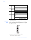
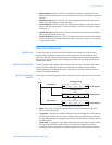
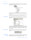
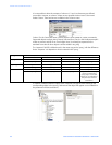
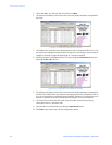
Memory Map
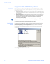
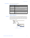
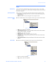
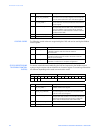
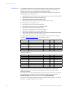
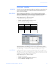
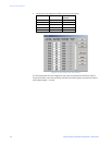
MEMORY LOCATIONS When configuring the sub-network, use the memory locations shown below:
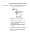
The PLC exchanges data
via the Profibus network
between its internal input
area and the input area
of the P485
Profibus network
The PLC exchanges data
via the Profibus network
between its internal output
area and the output area
of the P485
The data in the input area of
the P485 contains data received
from nodes on the Modbus
sub-network (sent in to the P485
from the sub-network)
The data in the output area of
the P485 contains data received
from Profibus. In this case, it is
the CT PRIMARY setting of the
PQMII meter.
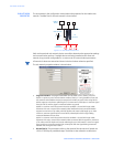
0x0000 0x0200 0x0400
Input data area Output data area General data area
Modbus sub-network
Current Ia CT PRIMARY
Internal memory buffer
of the P485
PLC memory
I/O inputs
I/O outputs
Current Ia
CT PRIMARY
Modbus slave (e.g. PQMII)
CT PRIMARY setting
Current Ia actual value
Address Contents Access
0x0000 to 0x0001 Status register read/write
0x0002 to 0x00F3 Input data area read/write
0x00F4 to 0x01FF Reserved -
0x0200 to 0x0201 Control register read only
0x0202 to 0x02F3 Output data area read only
0x02F4 to 0x03FF Reserved -
0x0400 to 0x7FF General data area read/write