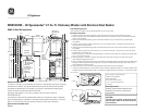
WSKS3040E – GE Spacemaker
2.1 Cu. Ft. Stationary Washer with Stainless Steel Basket
Specification Created 10/04
This kit consists of the following:
6-1/4 x 3 inch wood screws
7-1/4 x 1-1/2 inch wood screws
Carefully read and follow individual
installation instructions for exhausting
These instructions explain two mounting positions for your 24 inch dryer.
Obtain two pieces of 2x4 long enough to span at least two wall studs and the width of the dryer.
2. Locate wall stud center lines. Mark wall stud center lines on two pieces of 2x4 in relationship to position
Referring to dimensional drawing, draw a horizontal reference line (73") from the floor to locate upper
4. Position, level and secure upper 2x4 with four 1/4 x 3 inch wood screws. The bottom of the 2x4 should
be positioned on reference line.
, draw a horizontal reference line 32" down from the bottom of the upper
Position, level and secure lower 2x4 with two 1/4 x 3 inch wood screws. The center line of the 2x4 should
7. Referring to figure 1, mount the metal wall bracket 1/8 inch from the bottom of the upper 2x4 support with
five 1-1/2 inch wood screws.
Referring to figure 2, remove one screw from each lower rear corner of dryer and, using same screws,
lower brackets (supplied) as shown.
Dryer is supplied with exhaust at the top, locate and install outside exhaust duct referring to the dimensional
For other optional exhaust directions as shown in
dryer installation instruction sheet.
10. Position the dryer on the wall mounting bracket and check that the dryer is plumbed.
11. If the dryer needs plumbing, use some of the twelve washers supplied with the kit as spacers behind
brackets of figure 2 and secure the dryer to the lower 2x4 support using the remaining 1-1/2 inch
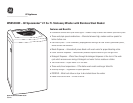
The back of the dryer is not accessible for service or maintenance after dryer mounting
installation is complete. It is recommended that the dryer be checked and electrical
installation completed prior to mounting. For service or maintenance requiring rear
access, the dryer must be removed from the wall.
CAUTION: DISCONNECT ELECTRICAL CURRENT BEFORE INSTALLING OR
The electrical outlet must be located above the dryer, or beside the dryer if adequate
is available. The outlet must be within three feet on a 240 volt
dryer or a 120 volt dryer from the service cord
entry on the rear of the dryer.
The 120 volt receptacle on the back of the
240 volt dryer must not be used with this
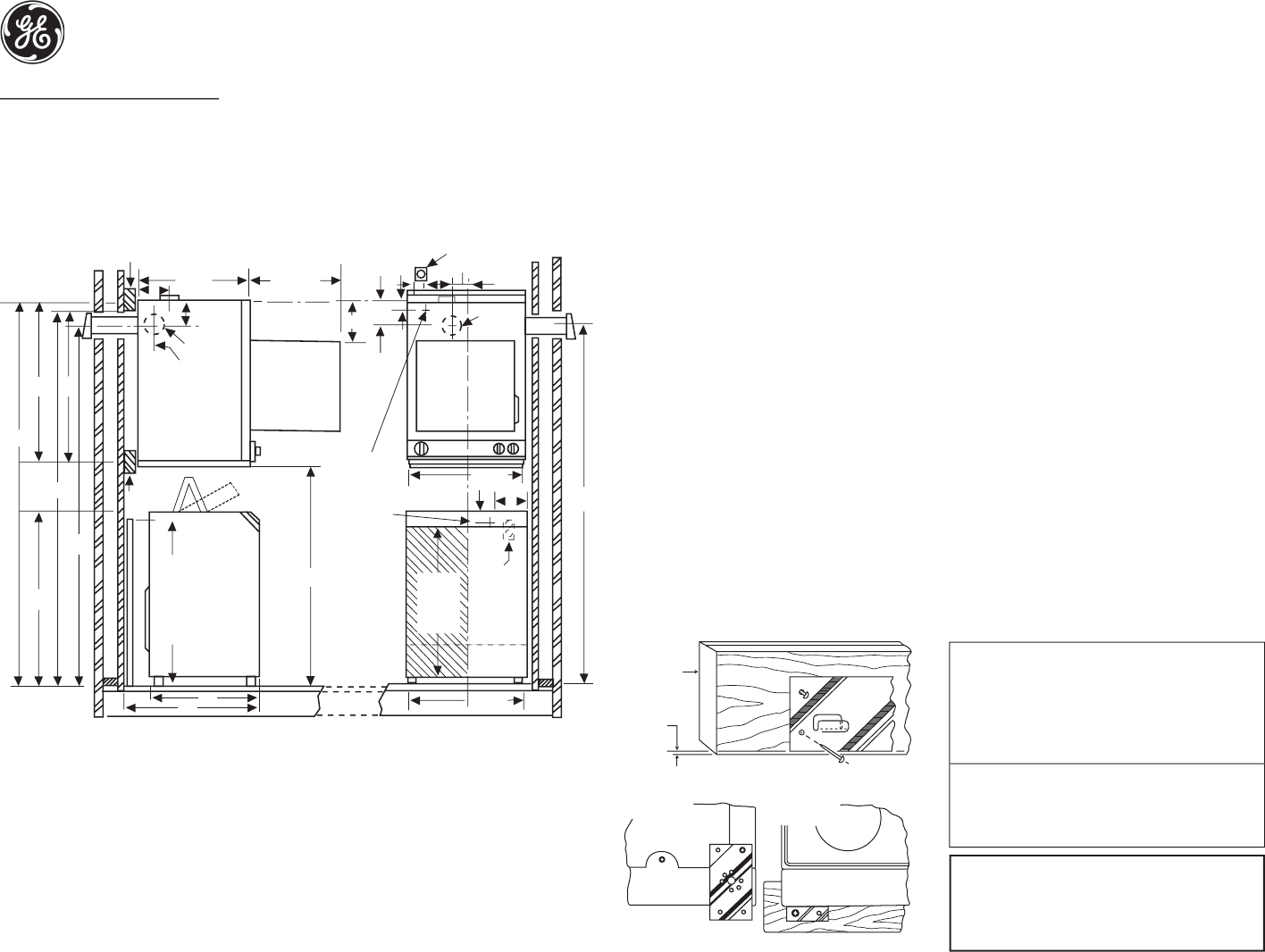
WALL BRACKET
REAR VIEW FRONT VIEW
2 x 4
figure 1
figure 2
wall_bracket_lineart.eps
1
/8" MAX
WMK-35 Wall Kit Installation
20" Max.
Opening
120V 20A or
208-240V 30A
3-3/4
3
3
Rear
Exhaust
5-1/8
8
74-1/8
78
74-1/8
Service
Cord
Entry at
Bank of
Appliances
R.H
EXH
5-1/8
4" Dia.
Exhaus
t
3-1/8
Both
Sides
33-1/
4
38
79-1/4
32
2 x
4
2 x
4
6
24-1/
2
DSKS433
DSKS333
WSLP1100
WSLS110
0
WSKS3040
Standpipe
33" Minimum
If Less Than 33"
Use Syphon
Break Kit
WH49X228
26
28
23-7/
8
6
120V
15 or 20A
1-1/2
23-5/8
Standpipe
& Faucets
33" Min.
portbl_or_statnry_bifl_wshr.eps
46