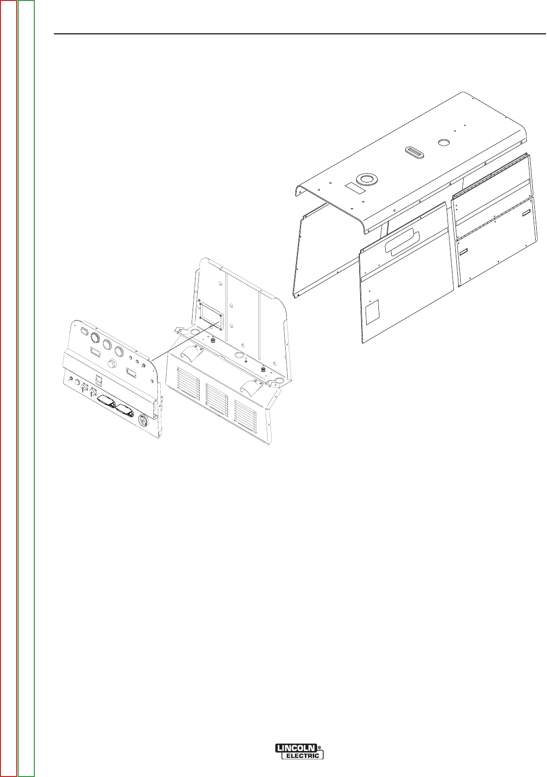
FIGURE F.10 – FRONT CONTROL PANEL REMOVAL
STATOR VOLTAGE TEST (CONTINUED)
PROCEDURE
1. Turn the engine off.
2. Using the 3/8" wrench, remove the screws holding
the front control panel to the case top and sides.
3. Carefully lower the front control panel.
4. Using the 3/8" wrench, remove the front left and
right side panels.
5. Using the 3/4" wrench, remove the internal leads
from the output terminals. Insulate the leads.
6. Using the 3/8" wrench, remove the screws holding
the lower front panel (output panel) to the case
front assembly. Then remove the front two screws
holding the top of the panel. These are accessed in
the control box, on the bottom at each side of the
box. See Figure F.10. Carefully move the lower
front panel to the right side. Note the green ground
lead will still be attached.
AUXILIARY POWER AND WELD WIND-
INGS TEST
Start the engine and run at high idle (1900 RPM). Do
not load welding or auxiliary power. See Figure F11
and the appropriate Wiring Diagram for test points.
Single Phase Auxiliary Machines
1. Check for 115-132VAC from:
Lead 6B on CB4 to lead 5B at Receptacle J12.
Leads 3A on CB3 to Lead 5B at ReceptacleJ12.
2. Check for 230 to 264VAC from lead 3A on CB3 to
lead 6B on CB4.
Three Phase Auxiliary Machines
1. Check for 230 to 246VAC from lead 3 to 6 on CB1.
2. Check for 230 to 246VAC from lead 3 to 4 on CB1.
3. Check for 230 to 246VAC from lead 4 to 6 on CB1.
4. Check for 115 to 132C from leads 3, 4, & 6 at CB1
to lead 5B at Receptacle J12.
TROUBLESHOOTING AND REPAIR
F-34 F-34
VANTAGE® 500
Return to Section TOC Return to Section TOC Return to Section TOC Return to Section TOC
Return to Master TOC Return to Master TOC Return to Master TOC Return to Master TOC


