OM-495 Page 32
Return To Table Of Contents
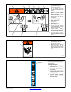
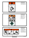
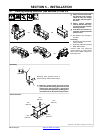
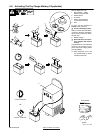
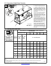
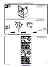
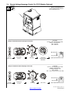
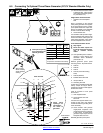
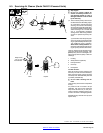
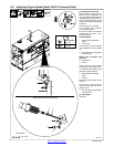
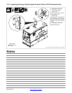
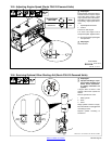
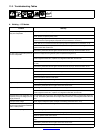
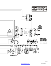
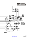
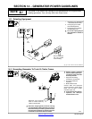
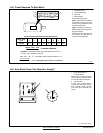
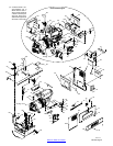
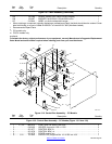
5-12. Connecting To Remote Amperage Adjust Receptacle RC13 On CC Models
Ref. 154 862-A / 048 720-K / 802 311
1 Remote Amperage Adjust
Receptacle RC13
Connect optional remote control to
RC13 (see Section 6-3).
1
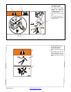
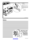
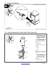
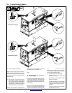
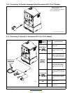
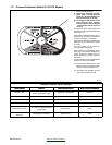
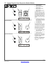
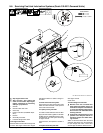
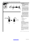
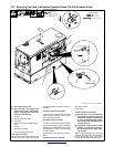
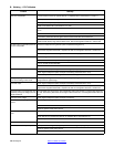
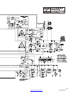
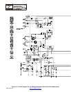
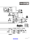
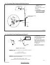
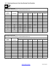
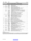
5-13. Connecting To Remote 14 Receptacle RC14 On CC/CV Models
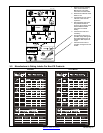
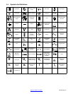
Socket* Socket Information
24 VOLTS AC
A 24 volts ac. Protected by circuit
breaker CB5.
B Contact closure to A completes
24 volt ac contactor control
circuit.
C Output to remote control:+10
volts dc in MIG or Stick mode;
0 to +10 volts dc in TIG mode.
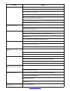
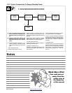
New! LDR-14 long
distance remote
REMOTE
TP
T
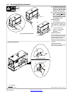
D Remote control circuit common.
(includes 120 V
receptacle)
CONTROL
E DC input command signal: 0 to
+10 volts from min. to max. of
remote control with Voltage/
Amperage Adjust control at
max.
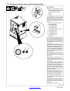
OR
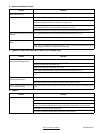
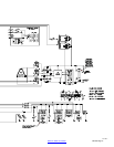
115 VOLTS AC
I
115 volts, 10 amperes, 60 Hz
ac. Protected by circuit breaker
CB6.
J
Contact closure to I completes
115 volt ac contactor control
circuit.
802 311
GND
K Chassis common.
NEUTRAL G Circuit common for 24 and 115
volt ac circuit.
*The remaining sockets are not used.