16
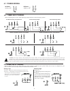
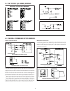
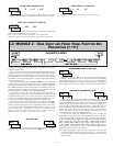
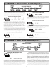
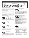
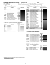
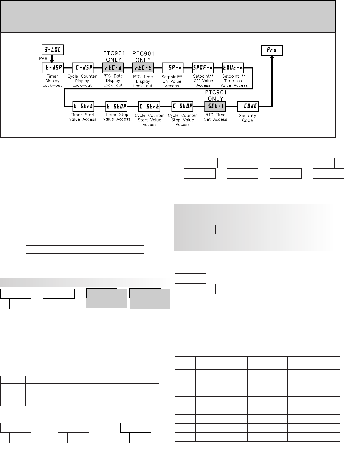
6.3 MODULE 3 - DISPLAY AND PROGRAM LOCK-OUT
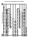
PARAMETERS ()
Module 3 is the programming module for setting the Display Lock-out
Parameters and the “Quick Programming Mode” Value Access Parameters. In the
Quick Programming mode, after the PROGRAM LOCKOUT PARAMETERS
and before the Security Code (), a Display Intensity Level ()
parameter is available when the security code is non-zero. It allows the display
intensity to be set to 1 of 16 levels (0-15).
ª
«
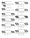
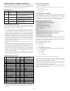
TIMER DISPLAY LOCK-OUT
CYCLE COUNTER DISPLAY LOCK-OUT
ª
«
ª
«
ª
«
These displays can be programmed for or . When a particular meter
function is not used, the Display Lock-out should be set to for that display.
Setpoint Values for SP1 thru SP4 can be programmed for
, , or .
and are only displayed when they apply to the Setpoint Action
() programmed for that particular Setpoint. (See Module 6 for details.)
ª
«
SETPOINT 1 to 4 VALUE ACCESS ** (
= 1 thru 4)
ª
«
ª
«
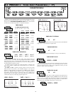
PROGRAM LOCK-OUT PARAMETERS (VALUE ACCESS)
“Full” Programming Mode permits all parameters to be viewed and
modified. This programming mode can be locked with a Security Code and/or
a User Input. When locked, and the PAR key is pressed, the meter enters a
Quick Programming Mode. In this mode, access to Setpoint Values, Timer &
Cycle Counter Start/Stop Values, and Time Setting for the Real-Time Clock can
be programmed for “Read”, “Enter”, or “Lock” defined as follows:
Timer & Counter Start/Stop Values can be programmed for , , or .
ª
«
TIMER & CYCLE COUNTER START/STOP VALUE ACCESS
ª
«
ª
«
ª
«
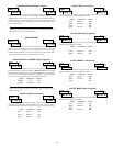
This parameter can be programmed for or . Selecting allows
setting or changing the RTC Time in Quick Programming mode.
ª
«
to
Entry of a non-zero value will cause the prompt to appear when trying
to access the “Full” Programming Mode. Access will only be allowed after
entering a matching security code or the universal unlock code of . With this
lock-out, a User Input would not have to be used for the Program Lock-out
function. Note however, the Security Code lock-out is overridden when an User
Input, configured for Program Lock-out (), is not active (See Chart.)
SECURITY CODE
ª
«
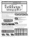
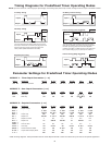
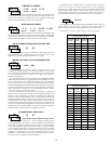
PROGRAMMING MODE ACCESS
Throughout this bulletin, Programming Mode (without Quick in front) always
refers to “Full” Programming.
Immediate accessFull ProgrammingNot Active
0
No accessQuick ProgrammingActive
0
Immediate accessFull ProgrammingNot Active
not 0
After Quick Programming
with correct Security
code entry
Quick ProgrammingActive
not 0
After Quick Programming
with correct Security
code entry
Quick Programming————
not
not 0
Immediate accessFull Programming————
not
0
FULL PROGRAMMING
MODE ACCESS
MODE WHEN “PAR”
KEY IS PRESSED
USER INPUT
STATE
USER INPUT
SELECTION
SECURITY
CODE
SELECTION DESCRIPTION
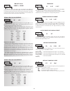
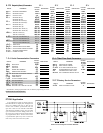
Read Visible, not changeable, in Quick Programming Mode
Lock Not visible in Quick Programming Mode
Enter Visible and changeable in Quick Programming Mode
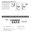
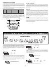
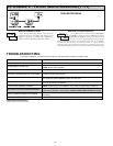
DISPLAY
DISPLAY LOCK-OUT PARAMETERS
When operating in the Display Mode, the meter displays can be viewed
consecutively by repeatedly pressing the DSP key. The annunciators to the left
of the display indicate which display is currently shown. Timer (TMR), Cycle
Counter (CNT), or Date (DAT). The Time Display for the Real-Time Clock is
shown with no annunciator. Any of these displays can be locked from view with
the DISPLAY LOCK-OUT parameters. Using these parameters, each display
can be programmed for “Read” or “Lock” defined as follows:
DISPLAY DESCRIPTION
Visible in Display Mode
Not visible in Display Mode
SELECTION
Read
Lock
** These parameters only appear if a Setpoint option card is installed.
= Setpoint Number 1 thru 4
PARAMETER MENU
PTC901: REAL-TIME CLOCK DATE/TIME DISPLAY LOCK-OUT
PTC901: REAL-TIME CLOCK TIME SETTING ACCESS