46
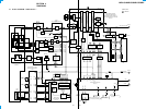
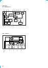
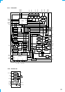
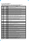
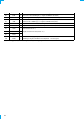
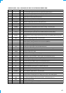
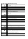
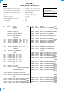
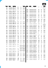
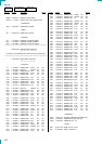
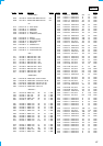
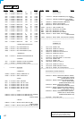
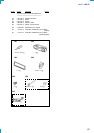
• MAIN BOARD IC501 MB90574PMT-G-266-BND (MASTER CONTROLLER)
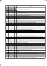
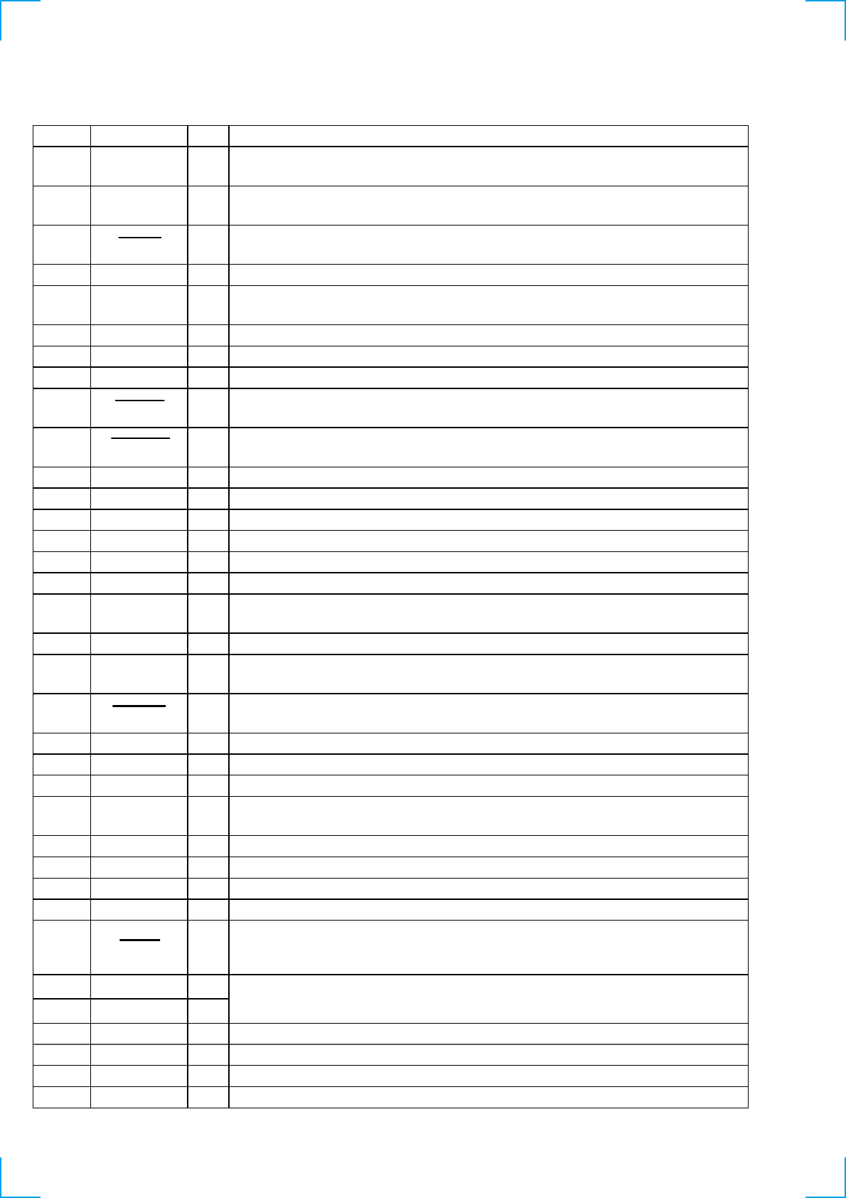
Pin No. Pin Name I/O Description
1
TUNON O
Tuner system power supply on/off control signal output to the BA4908 (IC671)
“H”: tuner power on
2 ANT CUT
O
Tuner system power supply on/off control signal output terminal “H”: tuner power on
Not used (open)
3 BUSON
O
Bus on/off control signal output to the MD mechanism controller (IC501) and SONY bus
interface (IC701) “L”: bus on
4 to 6 NCO O
Not used (open)
7
ILLON O
Power on/off control signal output of the illumination LED and liquid crystal display driver
(IC901) “H”: power on
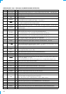
8VCC—
Power supply terminal (+5V)
9 E2P SIO I/O Two-way data E2P bus with the FM/AM tuner unit (TU1)
10
E2P CKO O
E2P bus clock signal output to the FM/AM tuner unit (TU1)
11 SYSRST O
System reset signal output to the MD mechanism controller (IC501) and SONY bus interface
(IC701) “L”: reset
12 DOORSW I
Front panel open/close detection signal input terminal
“L” is input when the front panel is closed
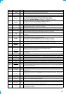
13 LCDSO
O Serial data output to the liquid crystal display driver (IC901)
14 LCDCKO
O Serial data transfer clock signal output to the liquid crystal display driver (IC901)
15 LCDCE
O Chip enable signal output to the liquid crystal display driver (IC901) “H” active
16
BEEP O Beep sound drive signal output to the power amplifier (IC611)
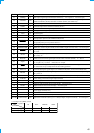
17 UNISI
I Serial data input from the SONY bus interface (IC701)
18 UNISO
O Serial data output to the SONY bus interface (IC701)
19 UNICKO
O
Serial clock signal output to the MD mechanism controller (IC501) and SONY bus interface
(IC701)
20
UNICKI I
Serial clock signal input from the MD mechanism controller (IC501) (for SONY bus)
21 CD MD
I
Setting terminal for the internal mechanism CD or MD
“L”: CD, “H”: MD (fixed at “H” in this set)
22
FLASHW
I
Internal flash memory data write mode detection signal input terminal “L”: data write mode
Not used
23 NCO O
Not used (open)
24
SIRCS
I
Sircs remote control signal input from the remote control receiver (IC951)
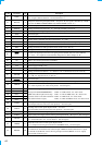
25 to 28 NCO O
Not used (open)
29 DOORIND
O
LED drive signal output of the MD disc slot illumination and Z indicator (LED810, LSW810)
“H”: LED on “H” is output to turn on LED when front panel is opened
30, 31 NCO O
Not used (open)
32 NS MASK O
Discharge control signal output for the noise detection circuit “H”: discharge
33
VSS
—
Ground terminal
34 C —
Connected to coupling capacitor for the power supply
35 AD ON
O
A/D converter power control signal output terminal
When the KEYACK (pin uh) that controls reference voltage power for key A/D conversion input
is active, “L” is output from this terminal to enable the input
36 REIN0
I
37 REIN1
I
38 DVCC —
Power supply terminal (+5V) (for D/A converter)
39 DVSS —
Ground terminal (for D/A converter)
40, 41 NCO O
Not used (open)
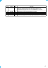
42 AVCC
— Power supply terminal (+5V) (for analog system)
Dial pulse input of the rotary encoder (RE901)
(for VOLUME/BASS/TREBLE/BALANCE/FADER control)