21
MZ-B100
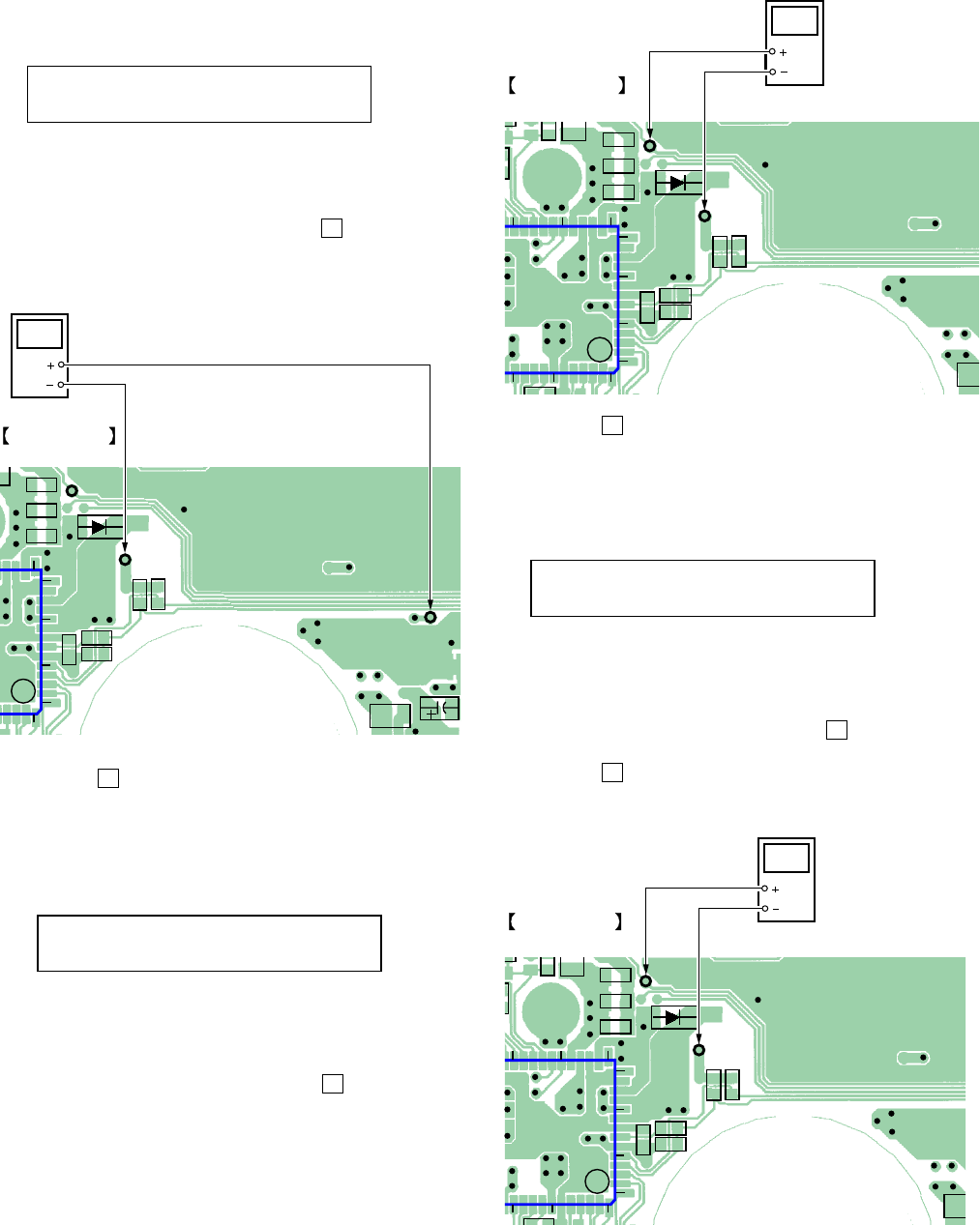
• Adjustment method of VC PWM Duty (H)
(mode number: 765)
1. Select the manual mode of the test mode, and set the mode
number 765. (See page 13)
2. Connect a digital voltmeter to the AP913 (VC) on the MAIN
board, and adjust
[EASY SEARCH +] key (voltage up) or
[EASY SEARCH --] key (voltage down) so that the voltage
becomes 2.75 ± 0.02 V.
Proceed to the next step without pressing X key if voltage is
already adjusted.
3. Press the X key to write the adjusted value.
• Adjustment method of VREM PWM Duty (H)
(mode number: 766)
1. Select the manual mode of the test mode, and set the mode
number 766. (See page 13)
2. Connect a digital voltmeter to the AP912 (VL) on the MAIN
board, and adjust [EASY SEARCH +] key (voltage up) or
[EASY SEARCH --] key (voltage down) so that the voltage
becomes 2.75 ± 0.02 V.
Proceed to the next step without pressing X key if voltage is
already adjusted.
15
56
14
10
5
1
C912
C913
C915
R919
R920
C924
C925
C926
R501
D903
C502
AP912
(VL)
AP909
(GND)
AP913
(VC)
digital
voltmeter
AP913 (VC)
AP909
(GND)
MAIN BOARD
(SIDE A)
VrlVch
767
LCD display
VrhVch
766
LCD display
45
50
25
20
15
56
14
10
5
1
IC901
C912
C913
C915
C
R919
R920
R9
C924
C925
C926
R5
D903
AP912
(VL)
AP909
(GND)
MAIN BOARD
digital
voltmeter
AP912 (VL)
AP909
(GND)
(SIDE A)
45
50
25
20
15
56
14
10
5
1
IC901
C912
C913
C915
C
R919
R920
R9
C924
C925
C926
R5
D903
AP912
(VL)
AP909
(GND)
MAIN BOARD
digital
voltmeter
AP912 (VL)
AP909
(GND)
(SIDE A)
VchPWM
765
LCD display
3. Press the X key to write the adjusted value.
• Adjustment method of VREM PWM Duty (L)
(mode number: 767)
1. Select the manual mode of the test mode, and set the mode
number 767. (See page 13)
2. Connect a digital voltmeter to the AP912 (VL) on the MAIN
board, and adjust [EASY SEARCH +] key (voltage up) or
[EASY SEARCH --] key (voltage down) so that the voltage
becomes 2.5 ± 0.02 V.
Proceed to the next step without pressing X key if voltage is
already adjusted.
3. Press the X key to write the adjusted value.


