


Connecting and Configuring Power 39
Connecting the PoE
Power Cord
Follow these steps to connect the power cord from the PoE rack:
1 Loosen the mounting screw of the PoE terminal block on the rear panel of the
switch.
2 Insert the -48V OT terminal of the DC power cord to the NEG (-) terminal of the
switch and fasten the mounting screw; insert the other end to the NEG (-) terminal
of the external PoE power supply. See
Figure 29 for a detailed view.
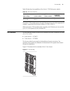
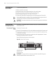
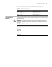
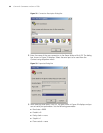
Figure 29 Back of the PoE Rack
1 PoE external power input: NEG (-)
2 (+) PoE external power input: NEG (+)
3 COM port (external power monitor)
3 Insert the GND OT terminal of the DC power cord to the RTN (+) terminal of the
switch and fasten the mounting screw; insert the other end to the NEG (-) terminal
of the site power.
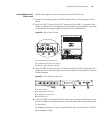
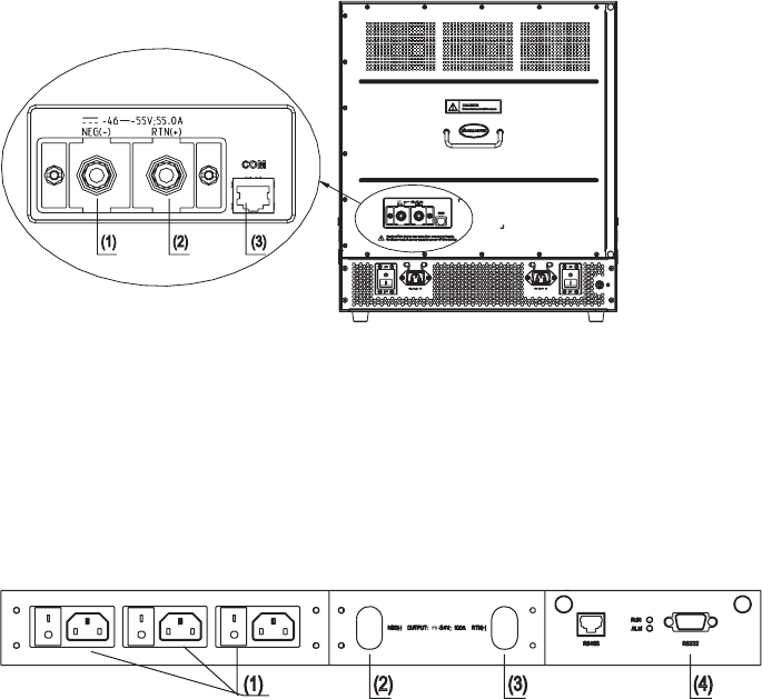
Figure 30 Front Panel of the PoE Rack
1 AC input socket
2 DC output terminal: NEG (-)
3 DC output terminal: RTN (+)
4 RS232 serial port
4 Insert the PGND OT terminal of the DC power cord to the grounding screw of the
switch and fasten the mounting screw; insert the other end to the grounding bar
for the switch.
For detailed instructions on how to install the PoE rack, see the Switch 7750 PoE
Rack Installation Guide.