


Installing the Fan Assembly 45
Installing the Fan
Assembly
To install the fan:
1 Wear an antistatic wrist strap.
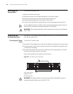
2 Remove the fan frame from the pack.
3 Hold the ejector levers on the fan frame with both hands and push them outward.
4 Align the fan with the guides in the chassis and slide it gently into the slot.
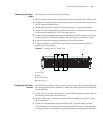
5 Push the fan until its positioning pin touches the hole in the chassis.
6 Push the ejector levers inward.
7 Push the handle bar pin into the hole in the chassis.
WARNING: To avoid injury, do not touch any naked wire, terminal, or any other
part of the product labelled Dangerous Voltage. Always wear the antistatic wrist
strap when installing the fan.
Installing Cables This section describes how to connect console and AUX cables to the Switch
7750.
Connecting the Console
Cable
The console cable is an 8-core shielded cable. One end of the cable has a crimped
RJ-45 connector, which is plugged into the console port of the switch. The other
end has both a DB-9-hole connector and a DB-25-hole connector for connection
to a 9-hole or 25-hole serial port at the configuration terminal.
See “Console Cable” on page 77 for cable illustration and pinout details.
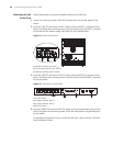
To connect a terminal or PC to the Switch 7750 using the console cable:
1 Plug the DB-9 or DB-25 female plug of the console cable to the serial port of the
PC or the terminal where the switch is to be configured.
2 Connect the RJ-45 connector of the console cable to the console port of the
switch.
Connecting the AUX
Cable
An AUX cable is used to connect the Switch 7750 to a modem in a remote dial-up
configuration.
The AUX cable is an 8-core shielded cable. One end of the cable is an RS-232
RJ-45 connector, which is used to plug into the switch at the console port. The
other end has both a DB-9-pin connector and a DB-25 pin for connection to a
9-hole or 25-hole serial port on the virtual modem.
See “AUX Cable” on page 77 for cable illustration and pinout details.
To connect the AUX cable:
1 Plug the RJ-45 end of the AUX cable into the switch console port.
2 Connect the DB-25 or DB-9 end of the AUX cable to the serial port of the virtual
modem.