


Placing Units On Top of Each Other 25
Placing Units On
Top of Each Other
If the Switch units are free-standing, up to four units can be placed one
on top of the other. If you are mixing a variety of 3Com equipment, the
smaller units must be positioned at the top.
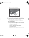
If you are placing Switch units one on top of the other, you must use the
self-adhesive rubber feet supplied. Apply the feet to the underside of
each Switch, sticking one in the marked area at each corner. Place the
Switch units on top of each other, ensuring that the feet of the upper unit
sit fully on the lower unit.
The Power-up
Sequence
The following sections describe how to get your Switch 4200G
powered-up and ready for operation.
Powering-up the
Switch 4200G
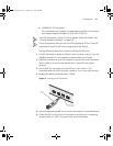
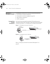
Use the following sequence of steps to power-up the Switch.
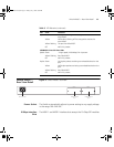
1 Plug the power cord into the power socket at the rear of the Switch.
2 Plug the other end of the power cord into your power outlet.
The Switch powers-up and runs through its Power On Self Test (POST),
which takes approximately one minute.
Checking for Correct
Operation of LEDs
During the Power On Self Test, all ports on the Switch are disabled and
the LEDs light. The PWR LED will flash green during the POST.
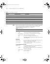
When the POST has completed, check the PWR LED to make sure that
your Switch is operating correctly. Table 7 shows possible colors for the
LED.
Table 7 PWR LED Colors
Color State
Green The Switch is powered-up and operating normally.
Red The Switch has failed its Power On Self Test (POST).
Yellow flashing Some ports have failed POST
*
* In this event you can still use the Switch using the remaining ports that have passed the
POST.
Off The Switch is not receiving power.
10014914AA.book Page 25 Friday, July 7, 2006 2:08 PM