


16 CHAPTER 1: INTRODUCING THE 3COM SWITCH 4050 AND 4060
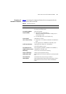
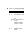
LEDs Table 4 lists LEDs visible on the front of the Switch, and how to read their
status according to color. For information on using the LEDs for problem
solving, see “Checking for Correct Operation of LEDs”
on page 26.
Table 4 LED behavior
LED Color Indicates
Port Status LEDs
Packet Yellow Packets are being transmitted/received on the port.
Off No packets are being transmitted/received on the port.
Status Green A high speed (1000 Mbps) link is present, and the port
is enabled.
Green flashing A high speed (1000 Mbps) link is present, but the port
is disabled.
Yellow A low speed (10/100 Mbps) link is present, and the
port is enabled.
Yellow flashing A low speed (10/100 Mbps) link is present, but the port
is disabled.
Yellow flashing
(fast)
Port has failed self-test and has automatically been
disabled.
Off No link is present.
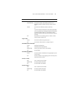
Module Status LEDs
Green The Module is installed and supported. The Link Status
has been determined for a single port Module.
Yellow The Module is installed and supported. The Module
has multi-ports or there is no link for a single port
Module.
Yellow flashing The Module is installed but not supported. Note that
the unit will continue to operate normally.
Yellow flashing
(fast)
A port on the Module has failed POST and has been
automatically disabled.
Off The Module is not installed.
Unit LEDs
1–4 Green Determines the identity of the Switch when
interconnected to another Switch to create a
Distibuted Fabric.
Off A fault has occurred.
Unit Status LED
Green The Switch is powered-up and operating normally.