


160 CHAPTER 16: MULTICAST CONFIGURATION GUIDE
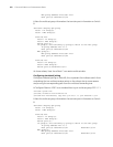
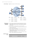
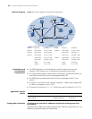
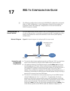
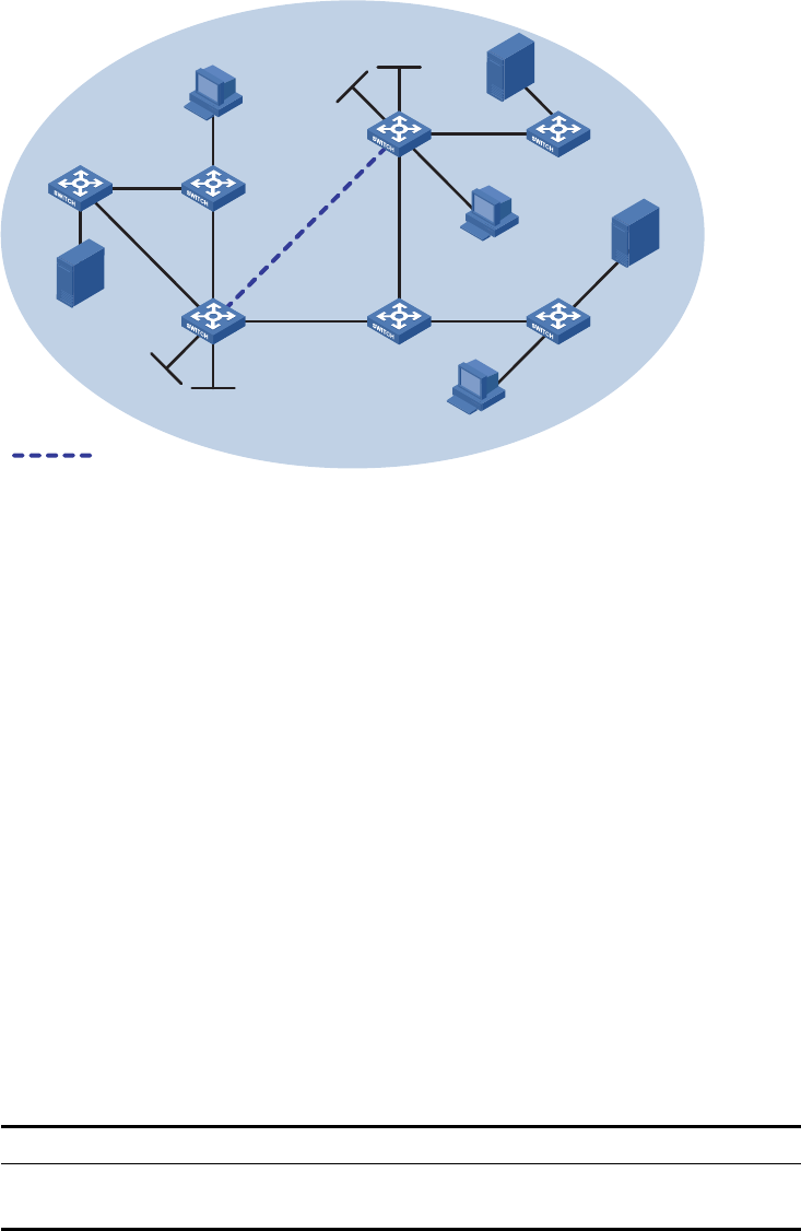
Network Diagram Figure 41 Network diagram for anycast RP configuration
Networking and
Configuration
Requirements
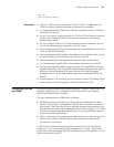
■ The PIM-SM domain in this example has multiple multicast sources and
receivers. OSPF needs to run in the domain to provide unicast routes.
■ The anycast RP application needs to be is configured in the PIM-SM domain, so
that the last-hop switch joins the topologically nearest RP.
■ An MSDP peering relationship needs to be set up between Switch C and
Switch F.
■ On Switch C and Switch F, the interface Loopback 1 needs to be configured as
a C-BSR, and Loopback 10 as a C-RP.
■ The router ID of Switch C is 1.1.1.1, while the router ID of Switch F is 2.2.2.2.
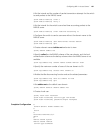
Application Product
Matrix
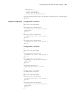
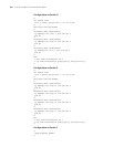
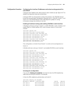
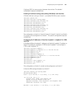
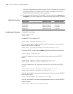
Configuration Procedure Configuring the interface IP addresses and unicast routing protocol for
each switch
Configure the IP address and subnet mask for each interface as per Figure 41. The
detailed configuration steps are omitted here.
Device Interface IP address Device Interface IP address
Switch A Vlan-int103 10.110.1.2/24 Switch D Vlan-int300 10.110.4.1/24
Switch B Vlan-int100 10.110.2.2/24 Vlan-int102 192.168.3.1
Switch C Vlan-int103 10.110.1.1/24 Vlan-int101 192.168.1.2/24
Vlan-int100 10.110.2.1/24 Switch F Vlan-int200 10.110.3.1/24
Vlan-int101 192.168.1.1/24 Vlan-int102 192.168.3.2/24
Loop1 3.3.3.3/32 Loop1 4.4.4.4/32
Loop10 10.1.1.1/32 Loop10 10.1.1.1/32
Source 2
Source 3
Receiver
Receiver
Receiver
Switch A
Switch B
Switch C
Switch D Switch E
Switch F
Switch G
Lo
o
p1
Loop10
L
o
o
p
1
Loop10
PIM-SM
MSDP peers
Vlan-int101
Vlan-int101
V
l
a
n
-
i
n
t
1
00
V
l
a
n
-
i
n
t
1
0
0
Vlan-int103
Vlan-int103
Vlan-int102
Vlan-int102
Vlan-int300
Vlan-int200
Source 1
10.110.5.100/24
Product series Software version Hardware version
Switch 5500 Release V03.02.04 All versions
Switch 5500G Release V03.02.04 All versions