


2 - 12 ONline Ethernet 10BASE-FL Installation and Operation Guide
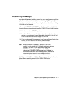
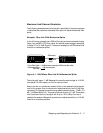
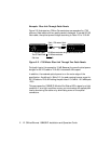
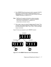
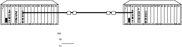
Example: Fiber Link Through Patch Panels
Figure 2-2 illustrates two ONline Concentrators are separated by 1700
meters of fiber cable with two patch panels in between. If we use 50/125
fiber cable, the optical power budget according to Table 2-3 is 10.0 dB.
.
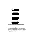
Figure 2-2. 1700 Meter Fiber Link Through Two Patch Panels
Total path loss in this example is 10 dB. Because the overall optical power
budget for 50/125 cable is 10.0 dB, this leaves 0 dB to spare.
In addition, the received optical power is on the outer edge of the
specification. As defined in Table 2-3, the peak received power range for
50/125 cable is -29.5 dB. Adding the path loss of 10.0 dB to -19.5 dB equals
-29.5.
This may cause the 10BASE-FL Module Port Status LED to signal a no light
condition. If a no light condition occurs, you must reduce the optical path
loss by shortening the cable or by eliminating some of the optical
connectors.
Panel
Patch
Panel
Patch
Connectors Connectors
1700 meters
8.5 dB loss worst case using 5 dB/Km loss fiber cable
1.5 dB loss worst case
1.7 Km Fiber Cable
Two ST Patch Panel
10.0 dBPath Loss