


2 - 22 ONline Ethernet 10BASE-FL Installation and Operation Guide
.
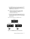
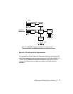
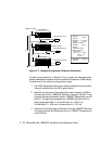
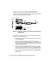
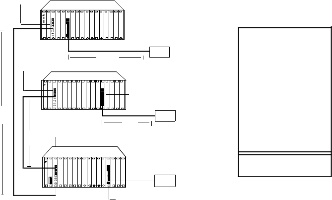
Figure 2-7. Sample Configuration Distance Calculation
To make the configuration in Figure 2-7 work, ensure the fiber equivalent
distance between transceiver A and transceiver B is less than 4200 meters.
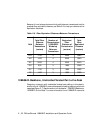
To determine if the network configuration is legal:
1. Use 4200 meters as the maximum network diameter for a pure fiber
network as defined by the 802.3 specification.
2. Subtract the equivalent fiber distance for each intervening ONline
Concentrator with a 10BASE-FL Module in the path. Figure 2-7 has
three concentrators between the two 10BASE-T Transceivers A and B
(Rule 4). The signal transverses three 10BASE-FL Modules from a
delay perspective (230 m on Concentrator A + 560 m on
Concentrator C + 330 m on Concentrator B = 1120 m).
3. Subtract the fiber equivalent distance for the two 10BASE-T Modules
in Concentrators A and B between the two 10BASE-T Transceivers A
and B (Rule 4).
Unshielded Twisted Pair
75 m
150 m
1000 m
500 m
Remaining
Distance
770 m
4200 m
585 m
Maximum
Diameter
10BASE-T
Modules
Distances Between
Transceivers
1.
3.
4.
A
B
Concentrator A
Concentrator B
Concentrator C
Unshielded Twisted Pair
A & B
2 m x 560 m
10BASE-FL2.
Equivalent Distance
Modules = 1120 m
Equivalent Distance
C
Unshielded Twisted Pair
230 m
330 m
560
m
500 m + 75 m
150 m + 1000 m
= 1725 m
- 10BASE-T Module
10BASE-FL Module
10BASE-FL Module
10BASE-FL Module
10BASE-T Module
10BASE-T Module