


Installing and Operating the Module 3 - 7
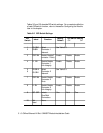
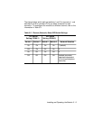
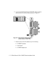
DIP Switch Description
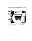
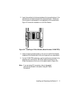
DIP switches are labeled 1 through 10 (refer to Figure 3-1). DIP switches 1
through 4 enable features for connector 1 (CONN 1). DIP switches 5
through 8 enable features for connector 2 (CONN 2). DIP switch 9 isolates
all ports (both connectors) from the backplane, or 12 ports on either
connector. Modules or ports set to the same network communicate with
each other.
Note: The DIP switch label on the module circuit board refers to
the backplane connection as “channel” (CH). This is the
“network” setting.