


26 CHAPTER 2: INSTALLING THE SWITCH
existing unit. If you do not initialize the unit, problems may be caused
by conflicting Switch configurations.
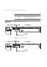
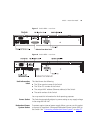
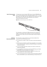
■ When the Switch units are interconnected they are assigned a unit
number dependent on which XRN Interconnect Cable end is
connected to which Switch. That is, the Switch with the blue cable
end will be assigned the identity of Unit 1 and the Switch with the
yellow cable end will be assigned the identity of Unit 2.
For a detailed description of how XRN Technology operates and
implementation guidelines, please refer to the Implementation Guide on
the CD-ROM that accompanies your Switch or on the 3Com Web site.
The Power-up
Sequence
The following sections describe how to get your Switch powered-up and
ready for operation.
Powering-up the
Switch
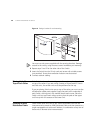
Use the following sequence of steps to power-up the Switch.
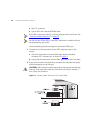
1 Plug the power cord into the power socket at the rear of the Switch.
2 Plug the other end of the power cord into your power outlet.
The Switch powers-up and runs through its Power On Self Test (POST),
which takes approximately 10 seconds.
Checking for Correct
Operation of LEDs
During the Power On Self Test, all ports on the Switch are disabled and
the LEDs light in a rapid sequence.
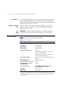
When the POST has completed, check the Power/Self Test LED to make
sure that your Switch is operating correctly. Table 6
shows possible colors
for the LED.
Table 6 Power/Self Test LED Colors
Color State
Green The Switch is powered-up and operating
normally.
Yellow The Switch has failed its Power On Self Test
(POST) because of an internal problem.
Off The Switch is not receiving power.