


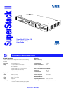
The SuperStack™ II Hub 10 Telco (3C16672A) has two 12 port Telco
connectors on the front panel providing Ethernet TP port connections,
and an AUI port on the rear panel. The rear panel also has a slot for a
3Com Transceiver Module or Bridge MicroModule: if fitted the module
will operate in addition to the AUI port. A range of different media
Transceiver Modules is available from 3Com (see
“
Products and Bulletin
Boards
”
).
The Hub 10 Telco can be stand-alone or linked with other Hub 10,
LinkBuilder FMS II, FMS, 10BT or 10BTi units to form a stack of units of
different media. Stacking units gives you the benefit of a higher port
count while the stack is still seen by the network as a single 802.3
repeater.
The Hub 10 Telco is suited for use in the office where it can be
wall-mounted, rack-mounted, or free standing. Alternatively, the unit can
be rack-mounted in a wiring closet or equipment room. A mounting kit
is supplied.
The Hub 10 Telco can be powered either from the AC mains supply, or
through an optional 3Com Redundant Power System (3C565047) to
provide a more reliable supply. Contact your local supplier for details.
Repeater Functions
The Hub 10 Telco has been designed to conform to the IEEE 802.3
standard for Local Area Networks. The unit provides all the standard
functions of an 802.3 repeater, including:
■
Signal retiming
■
Preamble regeneration
■
Fragment extension
■
Automatic partition/reconnection
Management
A SuperStack II Hub 10 Management Module (3C16630A) or Advanced
RMON Module (3C16632) can be fitted to the Hub 10 Telco to provide
f
ull SNMP management
, including statistics, resilient links and security
features
. Only one Management Module or Advanced RMON Module is
required for each stack. Refer to the guides accompanying the module
for details on how to manage an Hub 10 unit or stack.
Resilience and Security
H
ub 10 Management Module (3C16630A) and Hub 10 Advanced RMON
Module (3C16632) offer resilience
and security f
eatures.
Up to 16 resilient link pairs can be configured via management software.
To avoid the creation of loops during power-up, Hub 10 units provide a
Disable On Boot switch. If this switch is set to disable, all TP ports on the
unit will be disabled during power-up until they are correctly configured
and enabled by management software. This is only necessary on units
which have ports assigned as standby. Standby ports in resilient link
pairs can only be configured on SuperStack II Hub 10 or LinkBuilder
FMS II units.
Security features are described in the manual which comes with your
Hub 10 Management Module.
By disabling ports on boot up and enabling them with management
software, you provide extra security for your unit.
During the power up sequence, the main ports (on the front
panel) will be disabled, BUT the AUI and Transceiver Module
ports will be enabled for periods up to 1 second. During this
brief moment, the AUI and Transceiver Module ports will NOT
be secure.
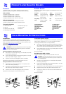
Network Connections
The Hub 10 Telco has been designed for use with the majority of known
Telco connectors.
Cable fixings have been supplied for holding the Telco cables to the
unit. There are locations for these fixings to the left of the Telco
connectors.
In the unlikely event that your Telco connector will not connect fully to
the Hub 10 Telco, we recommend that you:
■
Use a connector extension
■
Use a Telco connector with a different cable approach
You can connect any 802.3 transceiver to the unit using an AUI cable
connected to the AUI port on the rear panel. Alternatively, you can fit
one of the 3Com Transceiver Modules or a Bridge MicroModule into the
slot on the rear panel (see
“
Products and Bulletin Boards
”
).
You can connect the Hub 10 Telco to any other 10Base-T unit using port
24, to form an inter-repeater link. You must switch port 24 to MDI to
bypass the internal cross-over normally implemented by 10Base-T unit
ports. See
“
MDI Switch
”
.
Important
To manage this hub, you
may n
eed
a new v
ersion of the agent
software
installed on y
our Management Module.
See
“
Stack
Management
”
for details.
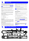
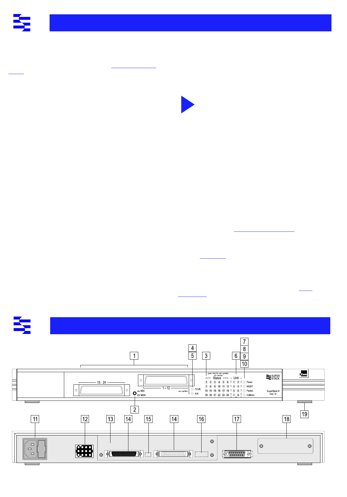
Numbered elements in this diagram refer to numbered sections in the text.
The numbers, in bold, are used as references in the text.
I
NTRODUCTION
H
OW
TO
U
SE
THE
H
UB
10
i