


Siting the Hub 10 Telco
CAUTION:
When installing the Hub 10 Telco in a stack with
FMS units, the Hub 10 Telco must be installed beneath any FMS
units.
When deciding where to site the Hub 10 Telco ensure:
■
It is accessible and cables can be connected easily.
■
Cabling is away from:
■
sources of electrical noise such as radios, transmitters and
broadband amplifiers.
■
power lines and fluorescent lighting fixtures.
■
Water or moisture cannot enter the case of the unit.
■
Air flow around the unit and through the vents in the side of the
case is not restricted (3Com recommend that you provide a
minimum of 25mm (1 inch) clearance).
To prolong the operational life of your units:
■
Never stack units more than eight high if free standing.
■
Do not place objects on top of any unit or stack.
■
Do not obstruct any vents at the sides of the case.
Rack or Wall Mounting
The Hub 10 Telco can be mounted in a 19 inch equipment rack or else
wall-mounted using the LinkBuilder Rack Mounting Kit. See
“
Rack
Mounting Kit Instructions
”
overleaf.
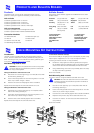
Stacking Units
The Hub 10 Telco can be linked to other Hub 10 units to form a stack, or
can be part of a mixed stack consisting of Hub 10, FMS, FMS II, 10BT or
10BTi units.
Different rules apply on stacking units if the stack only consists of Hub
10 and/or FMS II units compared to a stack with other mixed units.
Hub 10/FMS II only stacks
Up to 8 Hub 10 (FMS II) units can be linked together to form a free
standing stack or be mounted in a 19 inch rack, in a managed or
unmanaged configuration.
Only fit a Hub 10 or LinkBuilder FMS II Management Module or
Advanced RMON Module, to either the unit at the top or bottom of the
stack.
Mixed stacks of Hub 10/FMS II/FMS/10BT/10BTi
Link up to 8 units in a free standing stack or mounted in a rack. But any
FMS, 10BT or 10BTi units must be units 1-4 in a managed stack.
If mixing Hub 10 (FMS II) and FMS units in a free standing stack, the
narrower FMS units must be positioned at the top of the stack. This
restriction does not apply if rack mounting the units.
Stack Management
To manage any stack containing a Hub 10 unit, the Management
Module must have the correct version of the agent installed. The table
below details the minimum agent version numbers for each
management module.
Check which version you have installed before adding a Hub 10 unit to
your stack.
If you need to upgrade your agent, and a disk containing the new
versions is not included in the packaging, a free upgrade is available
from the 3Com bulletin boards (see
“
Products and Bulletin Boards
”
). The
upgrade includes instructions on how to load the agent.
Managing with an FMS Management Module
Managing with a Hub 10 (FMS II) Management
Module (3C16630A) or Advanced RMON Module
(3C16632)
If you have a Hub 10, LinkBuilder FMS or FMS II unit fitted with a
Management Module, and a LinkBuilder 10BTi in your stack, the Hub 10,
FMS or FMSII Management Module will manage the stack.
The LinkBuilder 10BTi can only manage LinkBuilder 10BT units
and the FMS Telco Hub (3C16271). 10BTi cannot manage other
FMS units or any Hub 10 (FMS II) units.
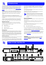
Power Up
Use the following sequence to power up the Hub 10 Telco:
■
Check the Disable On Boot switch at the rear and select position
as appropriate: see
15
.
■
Check the network connections and cables.
■
Check the hub expansion cables if in a stack.
■
Connect the power supply cable to the appropriate power socket
on the rear panel of the unit, see
11
or
12
.
■
Connect the plug to the power supply outlet socket and switch
on the power supply at the socket. If you are using a 3Com
Redundant Power Supply make sure it is switched on.
When the Hub 10 Telco is powered up, the Power LED should be lit. If it
is not, refer to
“
Power LED
”
,
9
.
Spot Checks
At frequent intervals you should visually check the Hub10 Telco. Regular
checks can give you an early warning of a possible failure; any problems
can then be attended to when there will be least effect on users. Check
the following:
What To Do Next?
If the Hub 10 Telco fails to operate successfully, contact your supplier
with the following information before returning the unit:
■
product number
■
serial number
■
a brief description of the fault
When returning any equipment to your supplier make sure the
equipment is packed suitably for transit.
3C16030
LinkBuilder FMS Management Module
3.04
3C16630
LinkBuilder FMS II Management Module
3.04
3C16630A
SuperStack II (FMS II) Management Module
3.14
3C16632
SuperStack II (FMS II) Advanced RMON Module
1.01
rack mounted stacks:
the module must be fitted to an FMS unit at
the top or bottom of the stack.
free standing stacks:
the module must be fitted to an FMS unit at
the top of the stack.
rack mounted stacks:
the module must be fitted to a Hub 10 (FMS II)
unit at the top or bottom of the stack.
free standing stacks:
the module must be fitted to a Hub 10 (FMS II)
unit at the bottom of the stack.
Cabling
Check that all external cabling connections are
secure and that no cables are pulled taut.
Cooling fans
Check that the cooling fans are operating and are
not obstructed. The fans are fitted to the right
hand side of the unit when viewed from the front.
Transceiver Module
Check that the Transceiver Module is connected
securely. Refer to the guide provided with the
Transceiver Module.
i