6
Important Safeguards (Continued)
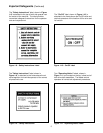
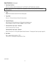
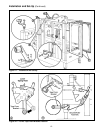
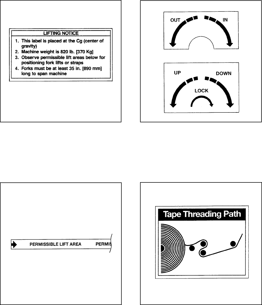
Figure 1-14 – Up/Down/Lock and In/Out Labels
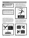
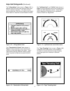
The "Lifting Notice" label, shown in Figure 1-12, is
attached to the left side of the machine frame close
to the air pressure regulator. This label reminds
service personnel of the center-of-gravity and weight
of the machine if machine must be lifted and moved.
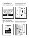
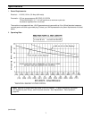
Two "Permissible Lift Area" labels shown in
Figure 1-13, are attached, two on each side of
machine, at the lower edge of the frame. These
labels remind service personnel where to place
forks if machine is lifted and moved with forklift
truck.
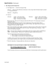
Figure 1-15 – Tape Threading Label
The "Up/Down/Lock" and "In/Out" labels shown in
Figure 1-14, are attached next to the corresponding
height and width adjustment cranks. These labels
remind operators of direction to turn adjustment
cranks to match box height/width.
Figure 1-12 – Lifting Notice Label
The "Tape Threading" label, shown in Figure 1-15,
is attached to the lower frame, at the infeed end.
This label is a quick reference for tape threading
when lower tape roll is mounted in outboard
position.
Figure 1-13 – Permissible Lift Area Label


