


Hardware Setup
iL-90MV 2-11
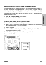
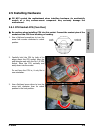
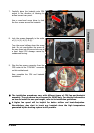
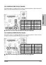
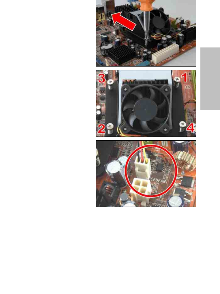
7. Carefully place the heatsink onto CPU
socket in the direction of blowing its
airflow toward rear panel.
Use a cross-head screw driver to lock
the four screws around the heatsink.
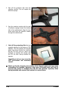
8. Lock the screws diagonally in the order
of (1) (2) (3) (4).
Turn the screw halfway down the screw
hole. Do not over-tighten the screw all
the way down into the screw hole one at
a time. Avoid CPU damage caused by
unbalanced forcing.
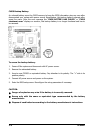
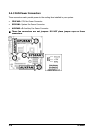
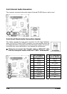
9. Plug the fan power connector from the
CPU cooler to the “CPUFAN1” connector
on this motherboard.
Now complete the CPU and heatsink
installation.
※ The installation procedures vary with different types of CPU fan-and-heatsink
assembly. The one shown here is served for DEMO only. For detailed information
on how to install the one you bought, refer to its installation guidelines.
※ A higher fan speed will be helpful for better airflow and heat-dissipation.
Nevertheless, stay alert to touch any heatsink since the high temperature
generated by the working system is still possible.