


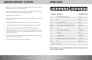
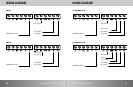
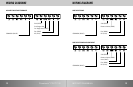
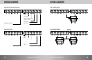
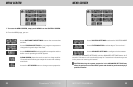

WIRING LEGEND
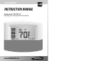
9INSTRUCTION MANUAL
TERMINAL EQUIPMENT STANDARD COLOR
Y1 First Heat Pump and AC Yellow
G Fan Green
W2 First Stage Furnace White
OBW Reverse Valve - Second Stage Furnace Orange
RH 24v Red
Y2 Second Heat Pump and AC Unknown
C Common Blue
H Humidity Control Unknown
DH Dehumidify Control, Variable Fan Control Unknown
RC 24v Unknown
11 and 12 Not Used
NOTE: The above colors are standard in HVAC industry. The wiring should be
confirmed before installation
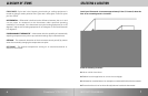
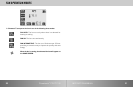
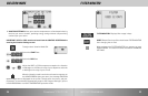
MOUNTING CLIMATOUCH
™
TO THE WALL
8 Climatouch
™
CT0-7TC-32
24V (RED)
2nd Stage Heat
1st Stage Heat (WHT)
Fan (GRN)
AC (YLW)
COMMON (BLUE)
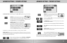
1. Make sure to turn off the power supply located at the electrical service panel.
All heating and cooling units should be OFF.
2. Separate the backplate from the thermostat by grasping the unit firmly at the
bottom lip and pulling gently until the two piece are apart.
3. Align the backplate to the wall.
4. Mark the three locations for drilling the 3/16” holes required for the plastic
screw anchors.
5. Remove the backplate and drill the three 3/16” holes in these locations.
6. Insert the plastic gyproc screws and ensure that they are snug in the wall.
7. Securely mount the backplate to the wall with the 3 supplied screws.
8. Make the appropriate wire connections based on the specifications of the
household HVAC unit(s). Please refer to Wiring Table to determine the appro-
priate wire connections.
9. Place the thermostat on the backplate by firmly but gently from the top aligning
the pins with the screw terminals.
10. Turn on the electricity at the electrical service panel.