


Page 3-1
Manual MPCICOM422-4.E1b
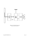
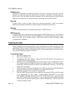
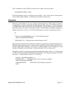
Figure 3-1: Simplified Termination Schematic
Chapter 3: Option Selection
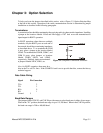
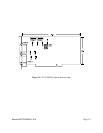
To help you locate the jumpers described in this section, refer to Figure 3-2, Option Selection Map
at the end of this section. Operation of the serial communications section is determined by jumper
installation as described in the following paragraphs.
Terminations
A transmission line should be terminated at the receiving end in its characteristic impedance. Installing
a jumper at the locations labeled LDxO and LDxI apply a 120? load across the transmit/receive
input/output for RS422 operation.
In RS422 operations where there are multiple
terminals, only the RS422 ports at each end of
the network should have terminating impedance
as described above. To so terminate the COM
A port, place a jumper at the location labeled
LDAO. To terminate the COM B, COM C, and
COM D ports, place jumpers at locations
labeled LDBO, LDCO, and LDDO
respectively. Similarly, inputs are terminated
at jumpers labeled LDAI, LDB1, etc.
Also, for RS422 operation, there must be a
bias on the Tx+ and Tx- lines. If the COM422/4 card is not to provide that bias, contact the factory
technical support.
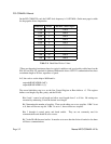
Data Cable Wiring
Signal Pin Connection
TX+ 2
TX- 3
RX+ 9
RX- 1
Ground 5
Baud Rate Ranges
The jumpers labeled CLK X1 and CLK X4 provide means to select baud rates in either of two ranges.
When in the "X1" position, the baud rate range is up to 115,200 baud. When in the CLK X4 position,
the baud rate range is 200 to 460,800 baud.