


Mechanical Operation
The shredder uses two rotating cutting shafts,
which are driven by an electrical motor to shred
paper.
Electrical Operation
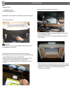
When the center power on switch is pressed,
all the LED warning symbols on the indicator
The shredder will now
be in standby mode and the “Power-on” symbol
on the indicator panel will be illuminated amber.
When the shredder is in standby mode and the the
cabinet door is opend,the normally closed door
adjar micro switch is opened and prevents power to
the motor until the door is closed.. When the bag full
sensor is triggered, the bag full icon will illuminate.
The control board will then disable the motor circuit
until the shredder bag is either cleared or emptied.
When the shredder is severely loaded down, the
control board will illuminate red and disable the
motor circuit.
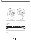
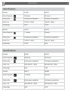
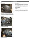
Electrical Components
Motor - Thermally protected motor designed for
continous operation.
Capacitor - AC motor run capacitor.
Power on/Auto feed on switch - The Power on
/Auto feed on switch, when depressed, connects
the hot and neutral circuits to electrical components
of the shredder.
Door ajar, Machine head safety switch - The safety
switch is a normally open micro switch which is
actuated by a trigger located inside of the cabinet door.
The switch is normally closed when the door is
closed and when the machine head is installed on the
cabinet.
Paper Sensors - Located in the throat area consist-
ing of two components, the emitter and receiver.
Emitter - The infrared light beam from the light emit-
ting diode is sensed by the receiver to activate/deac-
tivate the control board.
Receiver - The receiver is a light activated diode,
which works in conjunction with the emitter to acti-
vate/deactivate the control board.
Testin
g Electrical Components
WARNING!
Always disconnect the power cord from receptacle
before making continuity or resistance tests.
Switches
Set meter to read resistance. Check switches for
continuity from common to closed contacts and
ity from common to the open contact.
Emitter - Set meter to the diode setting. Disconnect
emitters from the control board. With the positive
meter probe on the emitter wire and the negative
meter probe on the black-stripped emitter wire,
check for approximately .639 ohms. Reverse the
meter leads and
should be read.
Receiver - Set meter to read 20M ohms. Disconnect
the receiver from the control board. With the positive
meter probe on the receiver wire and the negative
meter probe on the receiver wire check for app-
roximately 4.62 Mega ohms under normal room
light. The resistance will increase when blocked.
Reverse the meter leads and
should be read.
5.0 T
8
Troubleshooting
3
Bag Full Flap Switch - The ap switch is a normally
open switch actuated by the bag full ap. When the
shred bag becomes full of shredded material, the
bag full ap is pushed back and power is then
removed from the motor circuit.